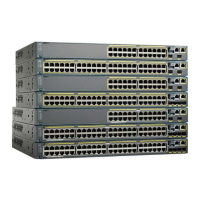
3. Place the switch on the table or shelf near an AC power source.
4. When you complete the switch installation, see After Switch Installation, on page 12for information on
switch configuration.
DETAILED STEPS
Step 1 To install the switch on a table or shelf, locate the adhesive strip with the rubber feet in the mounting-kit envelope.
Step 2 Attach the four rubber feet to the four circular etches on the bottom of the chassis.
Step 3 Place the switch on the table or shelf near an AC power source.
Step 4 When you complete the switch installation, see After Switch Installation, on page 12for information on switch
configuration.
After Switch Installation
• Configure the switch using the Configuration Setup wizard to enter the initial switch configuration.
• Install the power cord retainer (optional).
• Connect to the front-panel ports.
Installing the Power Cord Retainer (Optional)
The power cord retainer is optional (part number [PWR-CLP=]). You can order it when you order your switch,
or you can order it later from your Cisco representative.
SUMMARY STEPS
1. Choose the sleeve size of the power cord retainer based on the thickness of the cord. The smaller sleeve
can be snapped off and used for thin cords.
2. Slide the retainer around the AC power cord, and pass it around the loop on the switch.
3. Slide the retainer through the first latch.
4. Slide the retainer through the other latches to lock it.
5. (Optional) Use the small sleeve for thin power cords. Use the small sleeve to provide greater stability for
thin cords. Detach the sleeve, and slide it over the power cord.
6. Secure the AC power cord by pressing on the retainer.
DETAILED STEPS
Step 1 Choose the sleeve size of the power cord retainer based on the thickness of the cord. The smaller sleeve can be snapped
off and used for thin cords.
Step 2 Slide the retainer around the AC power cord, and pass it around the loop on the switch.
Switch Installation
12
Switch Installation
After Switch Installation
 Loading...


