2-13
Catalyst 3650 Switch Hardware Installation Guide
OL-29734-01
Chapter 2 Switch Installation
Installing the Switch
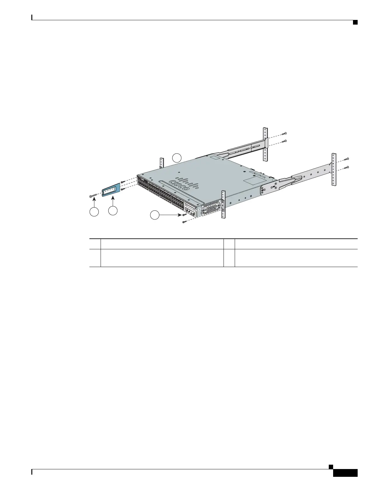
Mounting the Switch in a Rack
After the brackets are attached to the switch, use the supplied Phillips machine screws to attach the
brackets to the rack (Figure 2-10). Use the black Phillips machine screw to attach the cable guide to the
left or right bracket.
When you complete the switch installation, see the “After Installing the Switch” section on page 2-14
for more information switch configuration.
Figure 2-9 Mounting the Switch in a Rack
When you complete the switch installation, see the “After Installing the Switch” section on page 2-14
for more information about switch configuration.
1 Phillips machine screw, black 3 Front-mounting position
2 Cable guide 4 Number-12 or number-10 Phillips machine
screws
2
1
4
3
1
2
X
1
3
X
2
4
X
2
5
X
3
6
X
4
8
X
C
atal
y
s
t
365
0
48PoE+
2
X
10
G
3
7
X
1
X
347814
A
C
T
V

 Loading...


