EasyManuals Logo

Cisco Catalyst 3650 Series Guide

Cisco Catalyst 3650 Series
94 pages
To Next Page IconTo Next Page
To Previous Page IconTo Previous Page
Page #63 background imageLoading...
Page #63 background image
4-3
Catalyst 3650 Switch Hardware Installation Guide
OL-29734-01
Chapter 4 Installing the Fan
Fan Module Installation
Installing a Fan Module
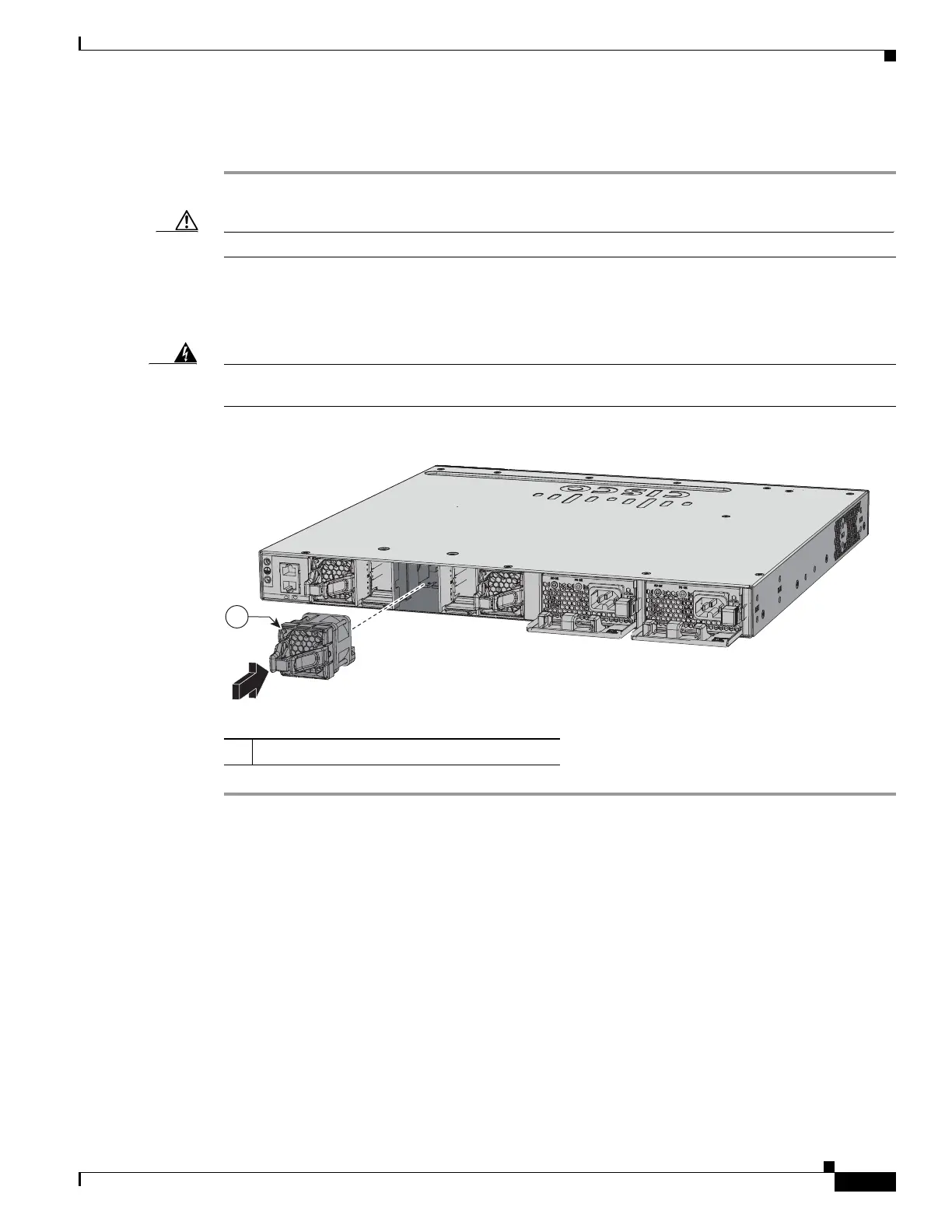
Step 1 Pinch the fan module release handle, and slide the module out.
Caution You should replace the fan module within 5 minutes to avoid overheating the switch.
Step 2 Install the fan module in the fan slot, and firmly push it into the slot, applying pressure to the end of the
module, not the extraction handles. When correctly inserted, the fan module is flush with the switch rear
panel. When the fan is operating, a green LED is on in the top left corner of the fan. See Figure 4-2.
Warning
Do not reach into a vacant slot when installing or removing a module. Exposed circuitry is an energy
hazard.
Statement 206
Figure 4-2 Installing the Fan Module
1 Fan LED
347794
PWR
-C2-6
40WAC
PWR
-C2-6
40WD
C
CONSOLE
MGMT
1

Table of Contents

Other manuals for Cisco Catalyst 3650 Series

Questions and Answers:

Question and Answer IconNeed help?

Do you have a question about the Cisco Catalyst 3650 Series and is the answer not in the manual?

Cisco Catalyst 3650 Series Specifications

General IconGeneral
RAM4 GB
Flash Memory4 GB
Ports24 or 48 10/100/1000 Ethernet ports
Uplinks4 x 1G SFP or 4 x 10G SFP+ (depending on model)
StackingUp to 9 switches with StackWise-160
Layer SupportLayer 2, Layer 3
SoftwareCisco IOS Software
Power SupplyInternal power supply; optional redundant power supply available
Storage Temperature-40°F to 158°F (-40°C to 70°C)

Related product manuals