If you use a 4x10G breakout cable, the ports default to 10 G interfaces.
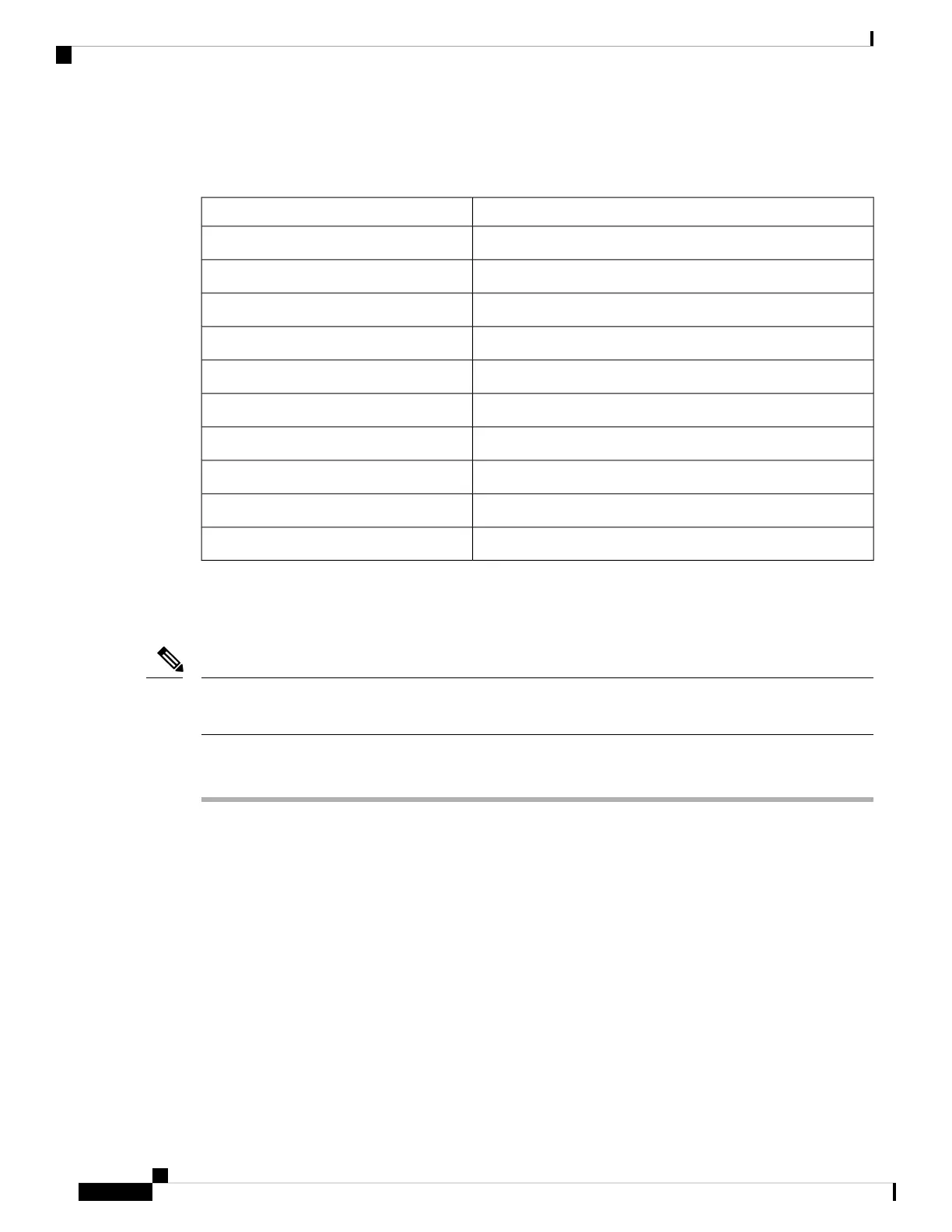
Table 28: C3850-NM-2-40G Module with 4x10G breakout cable
ActionInterface
DisregardFortyGigabitEthernet1/1/1
DisregardFortyGigabitEthernet1/1/2
Configure this interfaceTenGigabitEthernet1/1/1
Configure this interfaceTenGigabitEthernet1/1/2
Configure this interfaceTenGigabitEthernet1/1/3
Configure this interfaceTenGigabitEthernet1/1/4
Configure this interfaceTenGigabitEthernet1/1/5
Configure this interfaceTenGigabitEthernet1/1/6
Configure this interfaceTenGigabitEthernet1/1/7
Configure this interfaceTenGigabitEthernet1/1/8
Removing a Network Module
The switch complies with EMC, safety, and thermal specifications when a network module is present. If no
uplink ports are required, install a blank network module.
Note
Procedure
Step 1 Attach an ESD-preventive wrist strap to your wrist and to an earth ground surface
Do not remove the network module with connected cables or installed SFP/SFP+/SFP28/QSFP
modules. Always remove any cables and modules before you remove the network module.
Caution
A module interface might become error-disabled when a network module with connected fiber-optic
cables is installed or removed. If an interface is error-disabled, you can reenable the interface by
using the shutdown and no shutdown interface configuration commands.
Caution
Step 2 Disconnect the cables from the SFP/SFP+/SFP28/QSFP module.
Step 3 Remove the SFP/SFP+/SFP28/QSFP modules from the network module.
Step 4 Loosen the captive screws that hold the network module in place.
Cisco Catalyst 9300 Series Switches Hardware Installation Guide
50
Installing a Network Module
Removing a Network Module
 Loading...