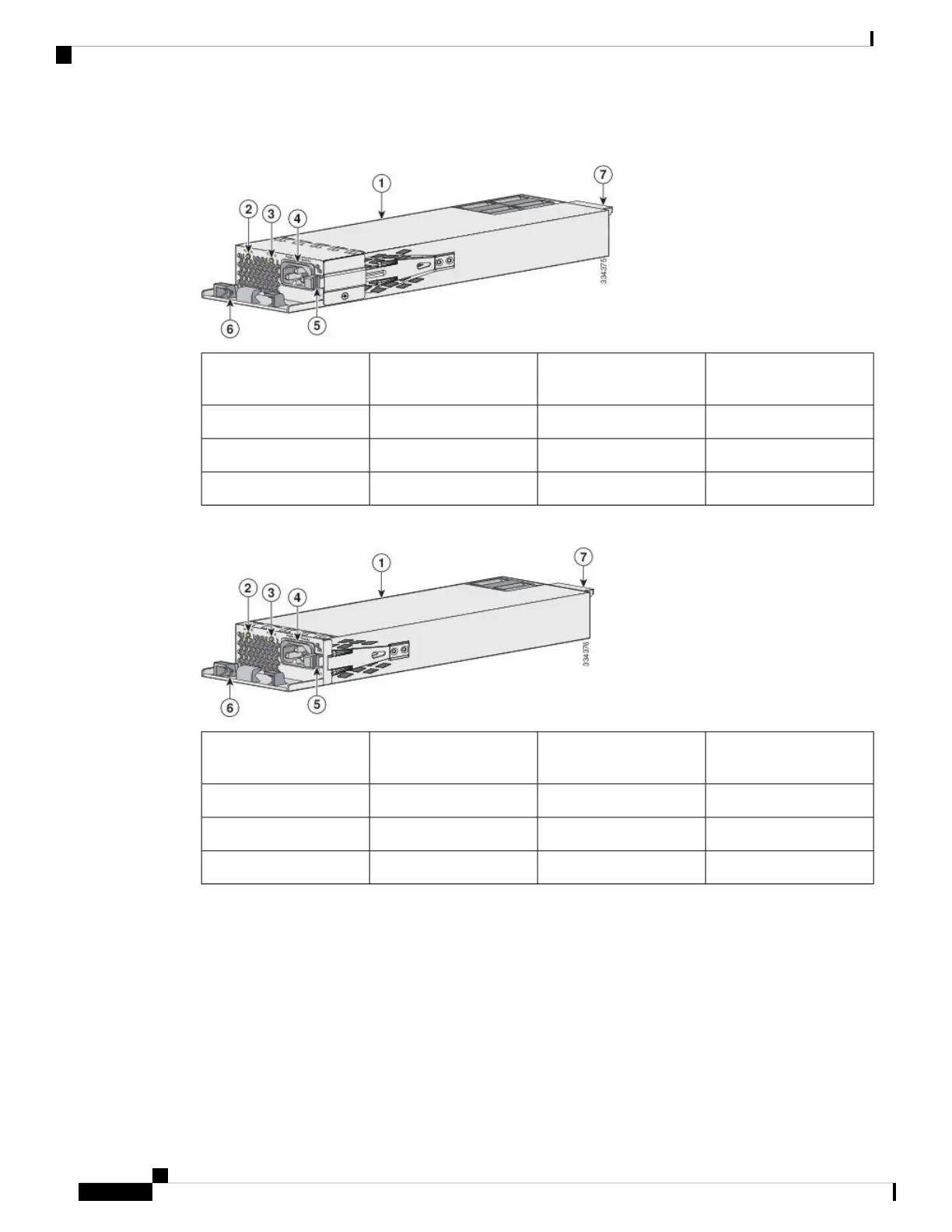
EasyManuals Logo

Cisco Catalyst C9300-48T User Manual

Cisco Catalyst C9300-48T
140 pages
To Next Page IconTo Next Page
To Previous Page IconTo Previous Page
Page #68 background imageLoading...
Page #68 background image
23-inch brackets (RACK-KIT-T1=)419-inch brackets (ACC-KIT-T1=)1
24-inch brackets (RACK-KIT-T1=)5Extension rails and 5 brackets for
four-point mounting, includes 19-inch
brackets (4PT-KIT-T2=)
2
--ETSI brackets (RACK-KIT-T1=)3
Attaching the Rack-Mount Brackets
Before you begin
You can use the minimum recommended number of two screws for installing the rack-mount bracket to each
side of the switch. If required, while mounting, you can use the additional four screws provided in the accessory
kit.
Procedure
Step 1 Use two Phillips flat-head screws to attach the long side of the bracket to each side of the switch for the front
or rear mounting positions.
Figure 30: Attaching 19-inches Rack Mount Brackets and Extension Rails
19-inch extension rail319-inch bracket1
--Number-8 Phillips flat-head screws
(48-2927-01)
2
Step 2 For Network Equipment-Building Standards (NEBS) compliant installations, perform the following steps:
Cisco Catalyst 9300 Series Switches Hardware Installation Guide
56
Installing a Switch
Attaching the Rack-Mount Brackets

Table of Contents

Questions and Answers:

Question and Answer IconNeed help?

Do you have a question about the Cisco Catalyst C9300-48T and is the answer not in the manual?

Cisco Catalyst C9300-48T Specifications

General IconGeneral
Total Ports48
Default AC Power Supply715W AC
Switching Capacity176 Gbps
DRAM8 GB
Flash Memory16 GB
Rack Units (RU)1 RU
Stacking Bandwidth480 Gbps
Weight7.25 kg
Power Supply Options1100W AC
Operating Temperature0 to 45°C
Operating Humidity5 to 90% relative humidity
Uplink Ports4 x 1G Network Module uplink ports (Optional)

Related product manuals