EasyManua.ls Logo

Cisco Catalyst IW9165E - User Manual

Cisco Catalyst IW9165E
16 pages
Print Icon
To Next Page IconTo Next Page
Loading...
Installation Overview
Preinstallation Checks and Installation Guidelines, on page 1
Mounting the Access Point, on page 2
Grounding the Access Point, on page 9
Powering the Access Point, on page 11
Connecting an Ethernet Cable to the Access Point, on page 13
Preinstallation Checks and Installation Guidelines
Before you mount and deploy your access point, we recommend that you perform a site survey (or use the
Site Planning tool) to determine the best location to install your access point.
You should have the following information about your wireless network available:
Access point locations
Access point mounting options: To a vertical or horizontal wall or a DIN rail
Access point power options: Use either of the following options to power the AP:
DC power input
Cisco-approved power injector
802.3at (PoE+), 802.3bt, and Cisco Universal PoE (Cisco UPOE)
Operating temperature: -40° to +158°F (-40° to +70°C) with still air.
Console access using the console port
We recommend that you use a console cable that is one meter or less in length.
The AP may face issues while booting if you use an unterminated console cable
(not plugged into any device or terminal) or a console cable that is more than one
meter in length.
Note
Installation Overview
1
Question and Answer IconNeed help?

Do you have a question about the Cisco Catalyst IW9165E and is the answer not in the manual?

Overview

This document provides an installation overview for a wireless access point (AP), likely the Cisco IW9165E, detailing preinstallation checks, mounting procedures, grounding, powering, and connecting an Ethernet cable.

Function Description:

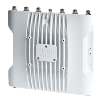
The device is a wireless access point designed for robust network connectivity. It supports various power options and mounting configurations, making it suitable for diverse deployment environments. Its primary function is to provide wireless network access, and it is designed to be integrated into existing network infrastructures. The AP is capable of operating in challenging temperature conditions, indicating its suitability for industrial or outdoor use.

Important Technical Specifications:

  • Power Input:
    • DC power: 24–48 VDC
    • Power-over-Ethernet (PoE): Supports 802.3at (PoE+), 802.3bt, and Cisco Universal PoE (Cisco UPOE).
    • The AP can be powered via a PoE input from an inline power injector or a suitably powered switch port.
  • Operating Temperature: -40° to +158°F (-40° to +70°C) with still air.
  • Mounting Hole Dimensions (Bottom of AP):
    • 54 x 4.900 inches
    • 1.84 x 1.384 inches
    • 4x M4 x 7, 15 MAX THREAD DEPTH
  • Wall Mounting Hole Dimensions (with brackets attached):
    • 7.28 x 6.80 inches
    • 1.40 x 1.07 inches
    • 2.00 x 1.385 inches
    • 0.25 x 0.208 inches
    • 0.28 inches
  • Grounding: Requires a 6-AWG ground wire and includes a grounding lug and 6-32 screws.
  • Console Cable: Recommended length of one meter or less. Using an unterminated or longer cable may cause booting issues.
  • Power Injector: The document mentions a "60W rated outdoor power injector, 5GE" (model IW-PWRINJ-60RGDMG) as a Cisco-approved option.
  • Ethernet Cable: Supports connecting an Ethernet cable via a cable gland or an M12-RJ45 adapter.
  • Radio Specifications (Cisco Catalyst IW9165E Feature Matrix):
    • 24-48V Power Input: 5G Radio (2x2), 5G/6G Radio (2x2), GNSS (Yes), mGig Eth (max 2.5G), RJ45 1G (Yes)
    • 802.3at Power Input: 5G Radio (2x2), 5G/6G Radio (2x2), GNSS (Yes), mGig Eth (max 2.5G), RJ45 1G (Yes)
    • 802.3af Power Input: 5G Radio (1x1), 5G/6G Radio (1x1), GNSS (Yes), mGig Eth (max 1G), RJ45 1G (No)

Usage Features:

  • Site Survey Recommendation: Before deployment, a site survey or the Site Planning tool is recommended to determine the optimal installation location.
  • Mounting Flexibility: The AP can be mounted in vertical or horizontal orientations.
    • Wall Mounting: Can be mounted to a wall or other flat surface using mounting brackets (x2) and M4 x 6mm screws. Torque for wall mounting screws is 12-15 inch-lbs.
    • DIN Rail Mounting: Can be mounted to a DIN rail, with the DIN rail kit ordered separately. The DIN rail can be installed in two different orientations (horizontally and vertically).
  • Airflow Clearance: A minimum of 1 inch clearance is required on all sides of the device (except the mounted side) for proper air flow, especially when wall or DIN rail mounted.
  • Powering Options: Supports both DC power input and Power-over-Ethernet (PoE) using a Cisco-approved power injector or a PoE-enabled switch.
  • Ethernet Connectivity: Connects to the network via an Ethernet cable. For specific industrial applications, an M12-RJ45 adapter can be used, requiring an O-ring and spacer for proper sealing and secure connection.
  • Console Access: Provides a console port for management and configuration.

Maintenance Features:

  • Grounding: The device requires proper grounding to prevent equipment damage and ensure safety. The grounding kit includes a grounding lug and screws, along with an oxide inhibitor for the connection.
  • Cable Management: Cables should be routed to avoid strain on connectors or mounting hardware, which helps prevent damage and ensures long-term reliability.
  • Secure Connections: Specific torque values are provided for mounting screws (12-15 inch-lbs for wall mounting, 15-20 inch-lbs for M12 adapter captive screws) and M12 adapter spacer screws (5-7 inch-lbs) to ensure secure and stable installations.
  • Environmental Resilience: The wide operating temperature range (-40° to +70°C) indicates the device's ability to withstand harsh environmental conditions, reducing the need for specialized climate control in many deployment scenarios.

Cisco Catalyst IW9165E Specifications

General IconGeneral
BrandCisco
ModelCatalyst IW9165E
CategoryWireless Access Point
LanguageEnglish

Related product manuals