53
Installing and Connecting the Router
Connectors and Cabling for the 8-Port Asynchronous/ Synchronous RS-232 GRWIC
RS-232 DB-9 Cable Pinouts
Table 13 on page 53 shows the pinouts for the CAB-9AS-M (High Density 4-port EIA-232 to DB-9, DTE) cable.
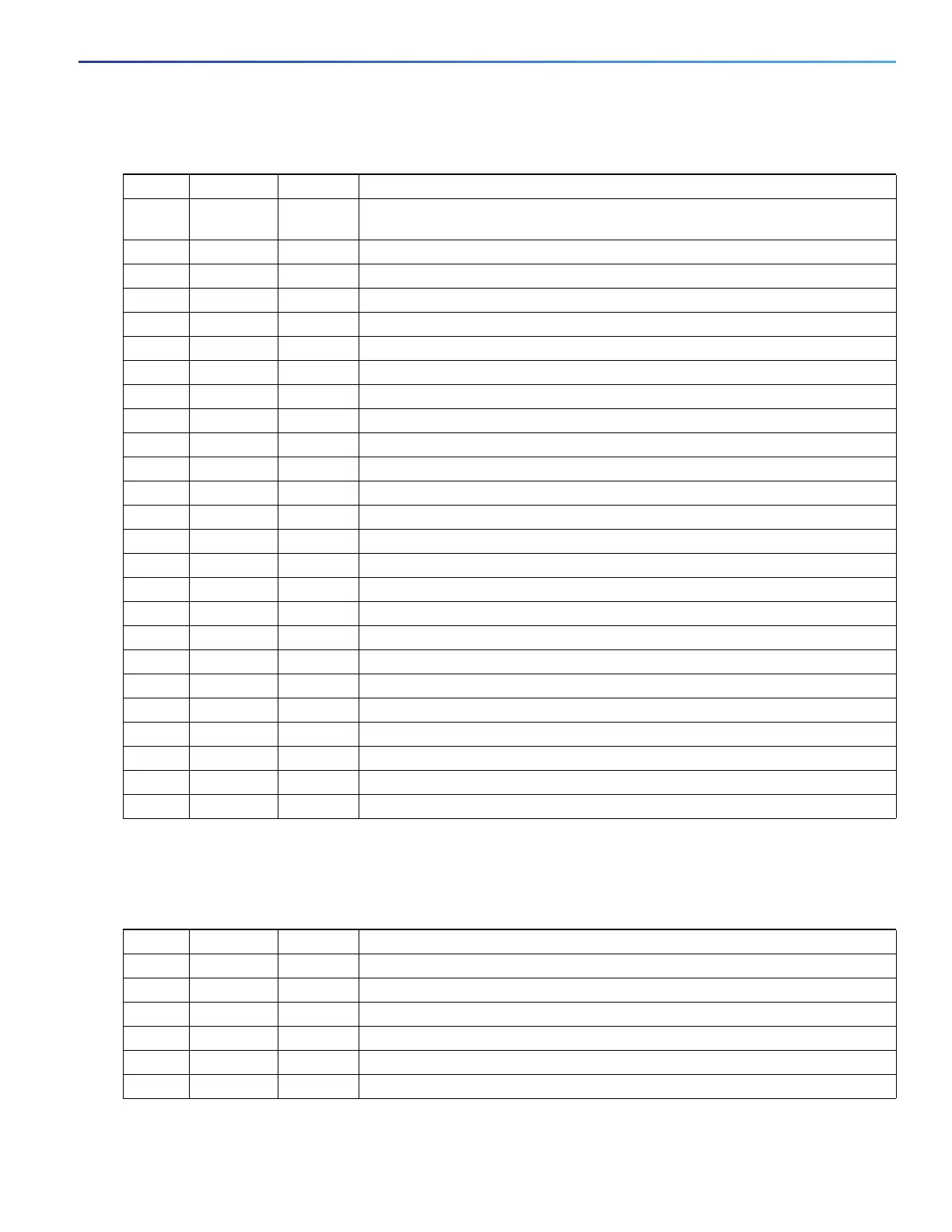
Table 12 Pinouts for Male and Female DB-25 Cables
Pin Signal Direction Description
1SHIELD
GND
— Shield Ground
2 TXD Input Transmit Data. Arriving data from DCE.
3 RXD Output Transmit Data. Sending data from DTE.
4 RTS Input Request to Send
5 CTS Output Clear to Send
6 DSR Output Data Set Ready
7GND— Ground
8 DCD Output Carrier Detect
9 — — Reserved for data set testing.
10 — — Reserved for data set testing.
11 — — Unassigned
12 — — Unassigned
13 — — Unassigned
14 — — Unassigned
15 TXC Output Transmit Clock
16 — — Unassigned
17 RXC Output Receive Clock
18 LTST Input Loopback Test (also Local Loopback)
19 — — Unassigned
20 DTR Input Data Terminal Ready
21 — — Unassigned
22 — — Unassigned
23 — — Unassigned
24 TXCE Input Transmit Clock Enable
25 — — Unassigned
Table 13 Pinouts for CAB-9AS-M (Male DB-9)
Pin Signal Direction Description
1— —
2 RD Input Receive Data. Arriving data from DCE.
3 TD Output Transmit Data. Sending data from DTE.
4— —
5 SGND — Ground
6— —