Make sure you have the correct firmware package and software version installed to support this network
module. For instructions on how to verify your firmware package version and to upgrade the firmware if
necessary, see the Cisco Firepower 4100/9300 FXOS Firmware Upgrade Guide. See Cisco Firepower 4100/9300
FXOS Compatibility for the software compatibility matrix.
Note
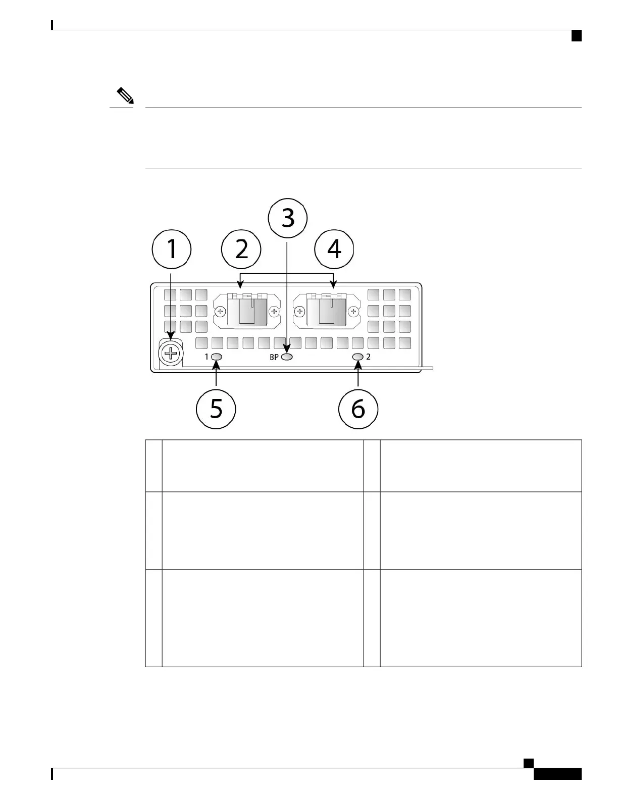
Figure 11: FPR4K-NM-2X40G-F
Ethernet X/1
Ports 1 and 2 are paired together to form a
hardware bypass pair.
2Captive screw/handle1
Ethernet X/2
Ports 1 and 2 are paired together to form a
hardware bypass pair.
4Bypass LED BP:
• Green—In standby mode.
• Amber, flashing—Port is in hardware bypass
mode, failure event.
3
Network activity LEDs for Pair 2:
• Amber—No connection, or port is not in use,
or no link or network failure.
• Green—Link up, no network activity.
• Green, flashing—Network activity.
6Network activity LEDs for Pair 1:
• Amber—No connection, or port is not in
use, or no link or network failure.
• Green—Link up, no network activity.
• Green, flashing—Network activity.
5
The following table describes the cable specifications needed to keep the insertion loss as low as possible.
Cisco Firepower 4110, 4120, 4140, and 4150 Hardware Installation Guide
17
Overview
40-Gb Network Module with Hardware Bypass
 Loading...


