EasyManuals Logo

Cisco Firepower 4110 Hardware Installation Guide

Cisco Firepower 4110
84 pages
To Next Page IconTo Next Page
To Previous Page IconTo Previous Page
Page #54 background imageLoading...
Page #54 background image
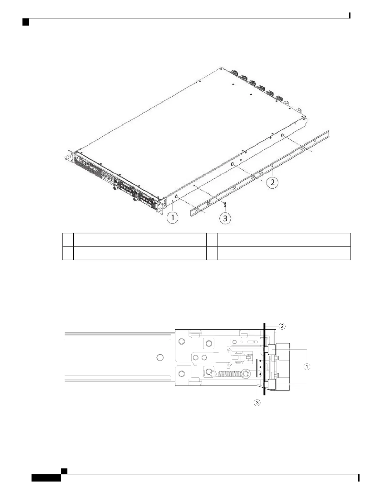
Figure 36: Attach the Inner Rail to the Side of the Chassis
Inner rail2Front of chassis1
M3 x 6-mm screw (one per side)3
Step 3 Open the front securing plate on both slide-rail assemblies. The front end of the slide-rail assembly has a spring-loaded
securing plate that must be open before you can insert the mounting pegs into the rack-post holes.
On the outside of the assembly, push the green arrow button toward the rear to open the securing plate.
Figure 37: Front Securing Mechanism Inside the Front End
Cisco Firepower 4110, 4120, 4140, and 4150 Hardware Installation Guide
50
Rack-Mount and Ground the Chassis
Rack-Mount the Chassis

Other manuals for Cisco Firepower 4110

Questions and Answers:

Question and Answer IconNeed help?

Do you have a question about the Cisco Firepower 4110 and is the answer not in the manual?

Cisco Firepower 4110 Specifications

General IconGeneral
Power SupplyDual, hot-swappable
Form Factor1RU
Firewall Throughput (Multiprotocol)10 Gbps
Number of 10GE (SFP+) Interfaces8
Number of 40GE (QSFP+) Interfaces2
Redundant Power SupplyYes
Memory32 GB
Ports8 x 10GE, 2 x 40GE
Concurrent Sessions8 Million
Number of 10/100/1000 Interfaces8
Maximum Connections8 Million
Management Ports1 x RJ45
Data Ports8 x 10GE, 2 x 40GE
ProcessorIntel Xeon E5-2600

Related product manuals