EasyManuals Logo

Cisco IE 1000 User Manual

Cisco IE 1000
52 pages
To Next Page IconTo Next Page
To Previous Page IconTo Previous Page
Page #12 background imageLoading...
Page #12 background image
8
Product Overview
Rear Panel
PoE Status LED
The PoE STATUS LEDs are located on the front panel of POE capable models. The LEDs display the functionality and
status of the adjacent PoE ports.
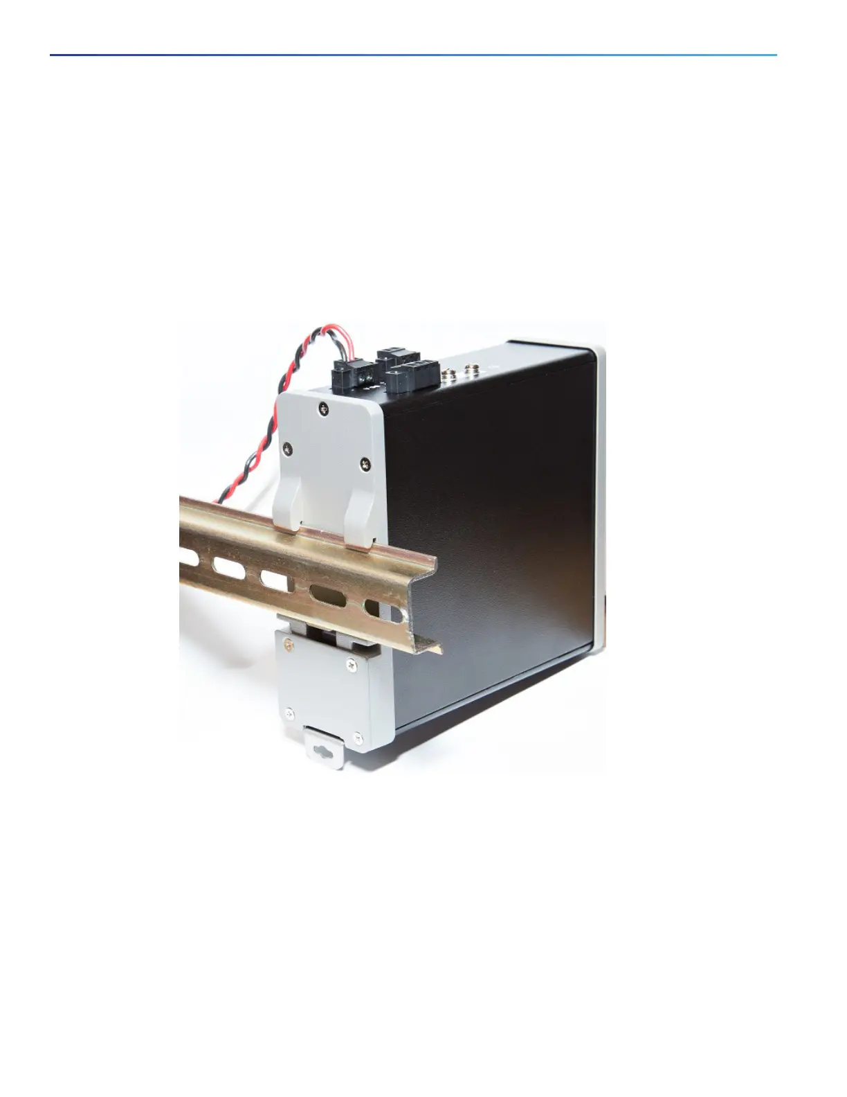
Rear Panel
The rear panel of the switch has a latch for installation on a DIN rail. See Figure 4 on page 8. The latch is spring-loaded
to move down to position the switch over a DIN rail and return to the original position to secure the switch to a DIN rail.
Figure 4 Cisco IE 1000 Switch Rear Panel
Management Options
The switch supports these management options:
Device Manager
You can use Device Manager, which is in the switch memory, to manage individual and standalone switches. This
web interface offers quick configuration and monitoring. You can access Device Manager from anywhere in your
network through a web browser.

Table of Contents

Questions and Answers:

Question and Answer IconNeed help?

Do you have a question about the Cisco IE 1000 and is the answer not in the manual?

Cisco IE 1000 Specifications

General IconGeneral
CategorySwitch
MountingDIN-rail or wall mounting
Dimensions90 x 135 x 55 mm (3.54 x 5.31 x 2.17 in)
DRAM256 MB
Flash Memory64 MB
ModelIE-1000
Ports8 or 16 10/100 Mbps ports
Uplink Ports2 Gigabit Ethernet uplink ports
Operating Temperature-40°C to 70°C
Power InputDual DC power input
ManagementWeb-based, CLI, SNMP
Total PortsVaries by model (5, 8, or 16 ports)
Power SupplyInternal
Weight1.1 lb

Related product manuals