21
Switch Installation
Connecting Alarm Circuits
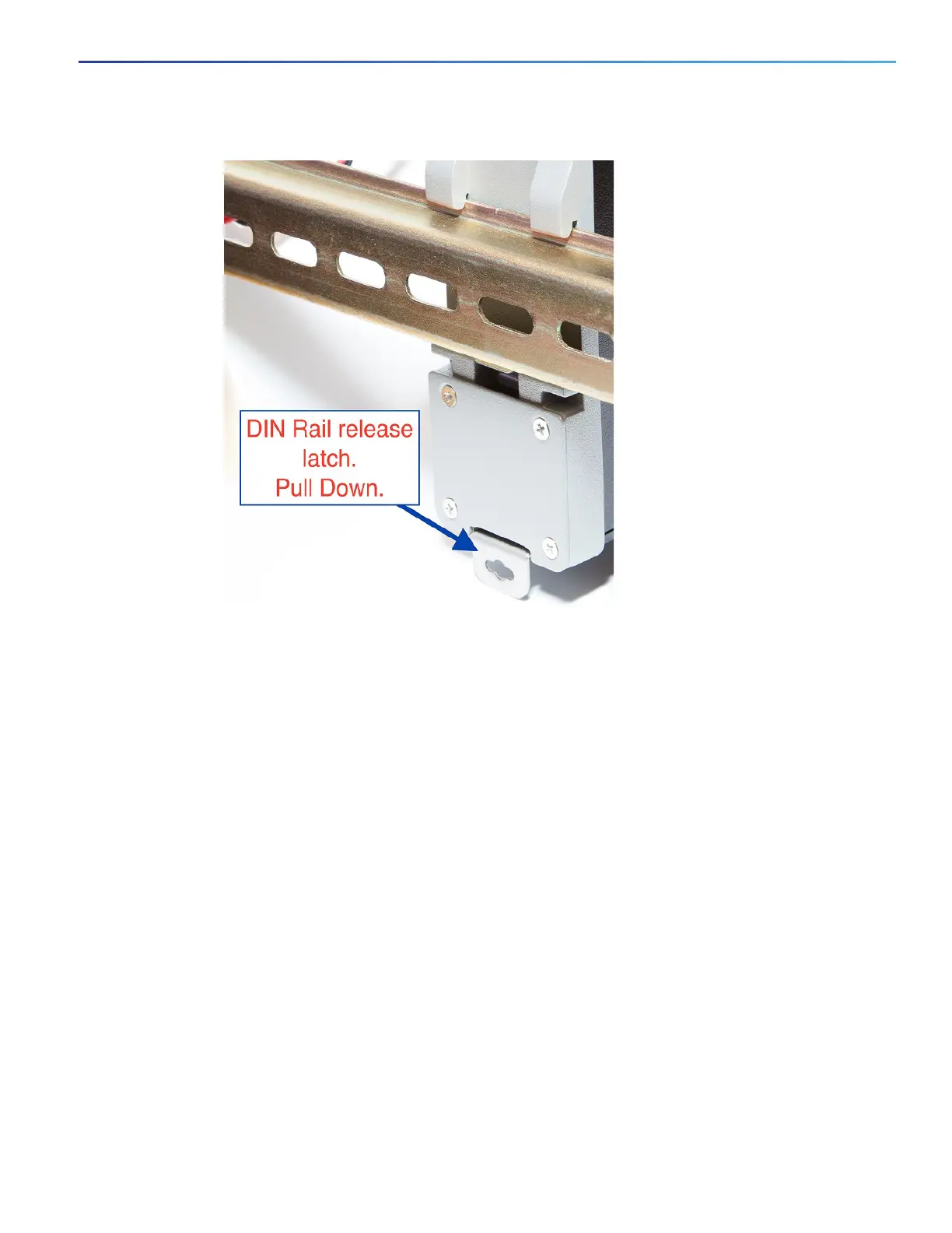
Figure 10 Releasing the Spring-Loaded Latch from the DIN Rail
4. Remove the switch from the DIN rail.
Connecting Alarm Circuits
After the switch is installed, you are ready to connect the DC power and alarm connections.
Wiring the Protective Ground and DC Power for Alarm Circuits, page 21
Wiring the External Alarms, page 21
Wiring the Protective Ground and DC Power for Alarm Circuits
For instructions on grounding the switch and connecting the DC power, see the Grounding the Switch, page 13.
Wiring the External Alarms
The switch has one alarm output relay circuit for external alarms. The alarm output relay circuit has a normally open and
a normally closed contact.
Alarm signals are connected to the switch through the 3-pin alarm connector. The three connections are for the alarm
output circuit: a normally open output, a normally closed output, and a common signal. An alarm output and the common
wiring connection are required to complete a single alarm output circuit.
The labels for the alarm connector are on the switch panel and are displayed below.

 Loading...


