LightStream 1010 ATM Switch Processor Module Configuration Note 17
Configuring the Interfaces
Switch” describes how to configure the ports on the FDDI or CDDI module. The section
“Confirming the Installation” describes the procedures you should use to confirm that the ASP is
configured correctly.
Port Addresses
Each interface (or port) in the switch is designated by several different types of addresses. The
physical interface address is the actual physical location (card/sub/port) of the interface connector
within the chassis. The system software uses the physical addresses to control activity within the
switch and to display status information. These physical card/subcard/port addresses are not used by
other devices in the network; they are specific to the individual switch and its internal components
and software.
The following sections describe how the LightStream 1010 switch assigns and controls both the
physical (card/subcard/port) and Media Access Control (MAC)-layer addresses for interfaces within
the chassis.
Port IDs
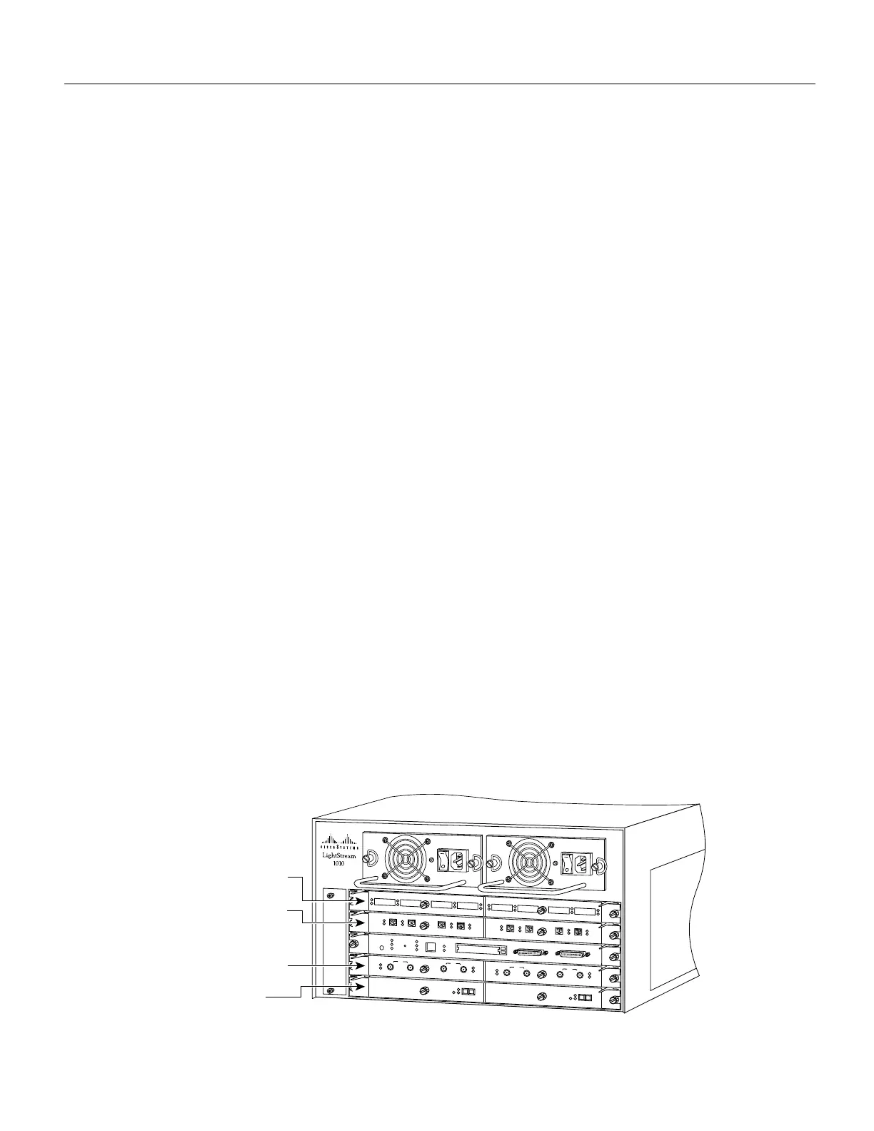
In the LightStream 1010 switch, port IDs specify the actual physical location of each PAM port on
the front of the switch. (See Figure 14.) The address is composed of a three-part number in the
format card/subcard/port number. The first number identifies the slot in which the module is
installed. Module slots are numbered 0 to 4 from top to bottom. The second number identifies the
subcard or PAM number. The PAMs are numbered 0 and 1 with 0 being the left PAM facing the front
of the switch. The third number identifies the physical port number on the module. The port numbers
always begin at 0 and are numbered from the left port to the right port, facing the front of the switch.
The number of additional ports (/1, /2, and so on) depends on the number of ports available on the
module.
Interface ports maintain the same port ID regardless of whether other modules are installed or
removed. However, when you move a module to a different slot, the first number in the address
changes to reflect the new slot number. For example, on a 4-port 155 UTP PAM in chassis slot 1 in
PAM slot 0, the address of the left port is 1/0/0 and the address of the right port is 1/0/3. If you
remove the 4-port 155 UTP PAM from slot 1 and install it in slot 4, the addresses of those same ports
become 4/0/0 and 4/0/3.
Figure 14 ATM Interface Port ID Address Examples
H5883
PS1
PS2
FAN
LINK
SLOT 2
SLOT 1
PCMCIA
EJECT
AUX
CONSOLE
Enet
RX
TX
RESET
SWITCH/PROCESSOR
TX
UTP3
UTP3
UTP3
UTP3
RX
UTP
TX
RX
TX
RX
TX
RX
1
2
3
TX
UTP3
UTP3
UTP3
UTP3
RX
UTP
TX
RX
TX
RX
TX
RX
1
2
3
TX
TX
RX
0
DS3
RX
TX
RX
TX
RX
1
DS3
DS3
TX
TX
RX
0
DS3
RX
TX
RX
TX
RX
1
DS3
DS3
622 SM
SM
TX
0
RX
CD
SM
TX
0
RX
CD
622 SM
0/0/0 to 0/0/3 and
0/1/0 to 0/1/3
1/0/0 to 1/0/3 and
1/1/0 to 1/1/3
3/0/0 to 3/0/1 and
3/1/0 to 3/1/1
4/0/0 to 4/1/0