14 LightStream 1010 ATM Switch Processor Module Configuration Note
Installing and Replacing the ASP
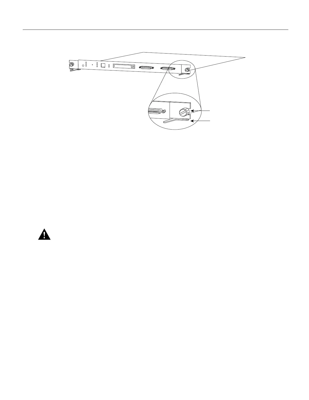
Figure 11 Ejector Levers and Captive Installation Screws (ASP Shown)
Tools Required
You need a 3/16-inch flat-blade screwdriver to remove any filler (blank) PAMs and to tighten the
captive installation screws that secure the ASP in their slots. Whenever you handle ASP you should
use a wrist strap or other grounding device to prevent electrostatic discharge (ESD) damage. See the
section “Preventing Electrostatic Discharge Damage” in the chapter “Preparing for Installation” in
the LightStream 1010 ATM Switch User Guide.
Removing the ASP
ASP and CAM removal instructions are the same, except only CAMs and PAMs support
hot-swapping.
Caution The ASP is a required system component. Removing an ASP while the system is
operating causes the system to shut down and may damage the processor. Power off the system
before removing the ASP.
Take the following steps to remove an ASP (or CAM):
Step 1 Loosen the captive installation screws, by using a screwdriver, at the left and right sides of
the ASP.
Step 2 Place your thumbs on the left and right ejector levers and simultaneously push the left lever
left and the right lever right to release the ASP from the backplane connector.
Step 3 Grasp the ASP faceplate with one hand and place your other hand under the carrier to
support and guide the module out of the slot. Avoid touching the card.
Step 4 Carefully pull the ASP straight out of the slot, keeping your other hand under the carrier to
guide it. Keep the module at a 90-degree orientation to the backplane.
Step 5 Place the removed ASP on an antistatic mat or antistatic foam.
Installing ASP
Slot number 2 contains the ASP, Figure 12, from top to bottom when viewing the chassis from the
front.
H5610
Captive installation
screws
Ejector lever
PS1
PS2
FAN
LINK
SLOT 2
SLOT 1
PCMCIA
EJECT
AUX
CONSOLE
Enet
RX
TX
RESET
SWITCH/PROCESSOR