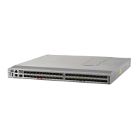
Figure 15: RJ-45 Interface Cable Connector
2. Pin
8
1. Pin
1
The following table lists the connector pinouts and signal names for a 10/100/1000BASE-T management port
(MDI) cable.
Table 11: 10/100/1000 BASE-T Management Port Cable Pinout
SignalPin
BI DA+1
BI DA-2
BI DB+3
BI DC+4
BI DC-5
BI DB-6
BI DD+7
BI DD-8
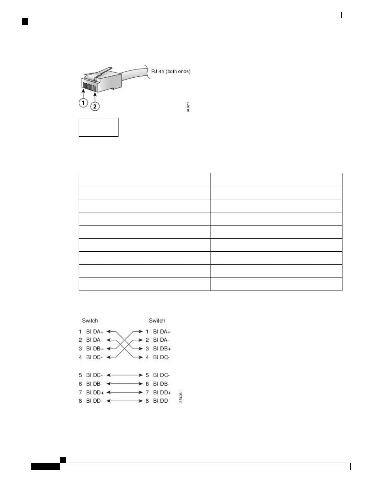
The following figure shows a schematic representation of the 10/100/1000 BASE-T cable:
Figure 16: Twisted-Pair 10/100/1000 BASE-T Cable
The following table lists the connector pinouts and signal names for a 10/100 BASE-T management port
(MDI) cable:
Cisco MDS 9124V-K9 Switch Hardware Installation Guide
50
Cable and Port Specifications
Cable and Port Specifications

 Loading...