B-5
Cisco ME 1200 Series Carrier Ethernet Access Devices Hardware Installation Guide
OL-31962-04
Appendix B Connector and Cable Specifications
Console Port Adapter Pin-outs
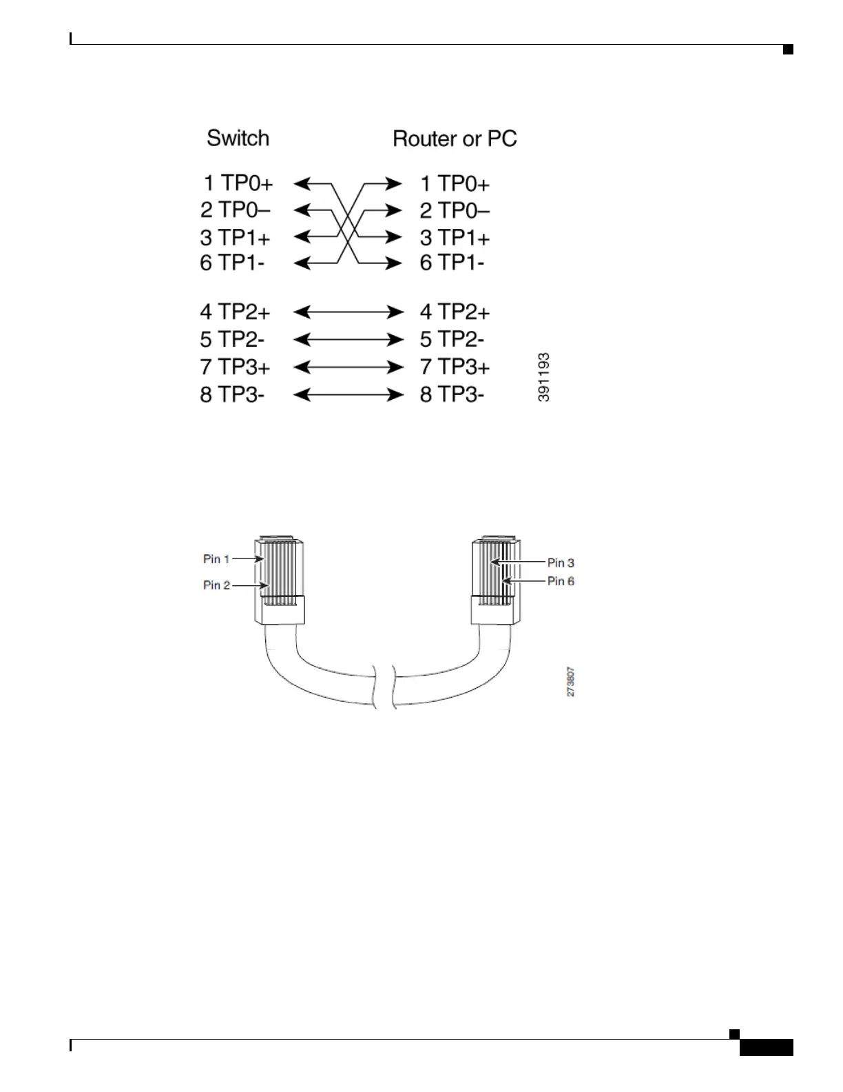
Figure B-8 Four Twisted-Pair Crossover Cable Schematics for 1000 Base-T Ports
To identify a crossover cable, compare the two modular ends of the cable. Hold the cable ends side-by-side,
with the tab at the back. The wire connected to pin 1 on the left plug should be the same color as the wire
connected to pin 3 on the right plug. The wire connected to pin 2 on the left plug should be the same color as
the wire connected to pin 6 on the right plug.
Figure B-9 Identifying a Crossover Cable
Console Port Adapter Pin-outs
The console port uses an 8-pin RJ-45 connector, which is described in Table B-3 and Table B-4. If you did
not order a console cable with your switch, you need to provide an RJ-45-to-DB-9 adapter cable to connect
the console port of the switch to a console PC. You need to provide an RJ-45-to-DB-25 female DTE adapter
if you want to connect the switch console port to a terminal. You can order a kit (part number
ACS-DSBUASYN=) containing that adapter from Cisco. For console port and adapter pin-out information,
see Table B-2 and Table B-3.
Table B-2 lists the pin-outs for the console port, the RJ-45-to-DB-9 adapter cable, and the console device.
 Loading...