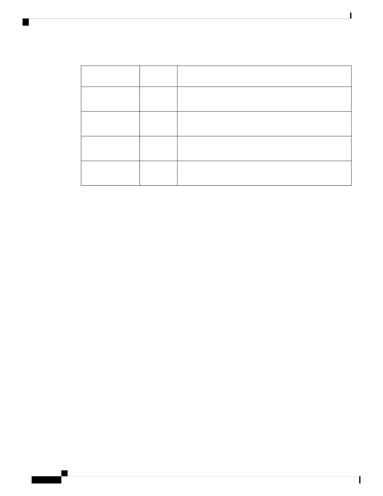
Table 1: Airflow Guidelines
Air ClearanceFlow
Direction
Router
At least 3 inches (76.2 millimeters) required on both inlet and exit
directions.
Right to LeftN540X-6Z18G-SYS-A
N540X-6Z18G-SYS-D
At least 3 inches (76.2 millimeters) required on both inlet and exit
directions.
Right to LeftN540X-8Z16G-SYS-A
N540X-8Z16G-SYS-D
At least 3 inches (76.2 millimeters) required on both inlet and exit
directions.
Right to LeftN540X-4Z14G2Q-A
N540X-4Z14G2Q-D
At least 3 inches (76.2 millimeters) required on both inlet and exit
directions.
Front to LeftN540-6Z18G-SYS-A
N540-6Z18G-SYS-D
Note the following points:
• When installing the router in a back-to-back position with another device, ensure that there is a minimum
of 3.9 inches (10 centimeters) airflow clearance between the two devices.
• If airflow through the equipment rack and the routers that occupy it is blocked or restricted, or if the
ambient air being drawn into the rack is too warm, an overtemperature condition may occur within the
rack and the routers that occupy it.
• The site must be as dust-free as possible. Dust tends to clog the router fans, reducing the flow of cooling
air through the equipment rack and the routers that occupy it, thereby increasing the risk of an
overtemperature condition.
• Enclosed racks must have adequate ventilation. Ensure that the rack is not congested because each router
generates heat. An enclosed rack must have louvered sides and a fan to provide cooling air. The equipment
generates heat near the bottom of the rack, which can be drawn upward into the intake ports of the
equipment above.
• When mounting a router in an open rack, ensure that the rack frame does not block the exhaust fans.
• When rack-installed equipment fails, especially equipment in an enclosed rack, try operating the equipment
by itself, if possible. Power off all the other equipment in the rack (and in adjacent racks) to give the
router maximum cooling air and clean power.
• Avoid installing the router in a location in which the router air intake vents may draw in the exhaust air
from adjacent equipment. Consider how the air flows through the router; the airflow direction is front to
back, with ambient air drawn in from the vents located on the sides of the router.
Site Power Guidelines
The chassis has specific power and electrical wiring requirements. Adhering to these requirements ensures
the reliable operation of the system. Follow these precautions and recommendations when planning your site
power for the chassis:
Prepare for Installation
6
Prepare for Installation
Site Power Guidelines

 Loading...


