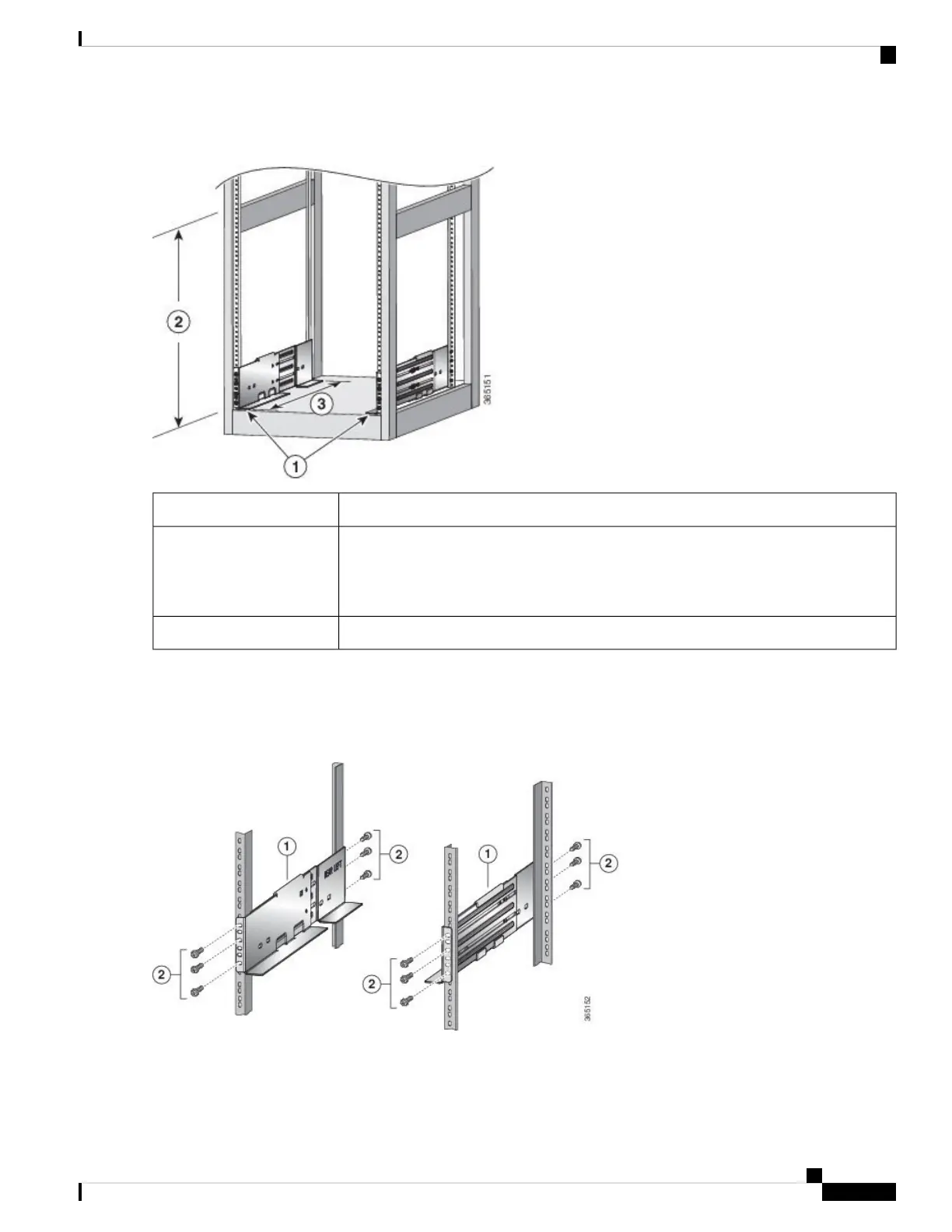
Figure 8: Position Bottom-Support Rails
Position two bottom-support rails at the lowest RU on the rack.1
NCS 5504: Allow at least 7.1 RU (12.43 inches [31.6 cm]) for each chassis.
NCS 5508: Allow at least 13 RU (22.7 in [57.8 cm]) for each chassis.
NCS 5516: Allow at least 21 (36.7 in [93.21 cm]) RU for each chassis.
2
Distance between front and rear vertical rails must be 24 to 32 inches (61.0 to 81.3 cm).3
Step 2 Attach the bottom-support rail to the rack using a Phillips torque screwdriver on three M6 x 19 mm or 12-24 x 3/4 inch
screws for each end of the rail (using a total of 6 screws for the rail as shown in the following figure) and tighten each
screw to 40 in-lbs (4.5 N.m) of torque.
Figure 9: Attach Bottom-Support Rails to a Rack
Hardware Installation Guide for Cisco NCS 5500 Series Modular Routers
33
Install the Chassis
Install Bottom-Support Rails