• Wire stripping tool
• Crimping tool
• Torque screwdriver and wrench
Step 1 Turn off the switch and circuit breaker as follows:
a) Turn the power switch on the power supply to standby (labeled 0 on the power supply).
b) Turn off the circuit breaker for each of the two power inputs coming from the DC power source.
Step 2 Connect the four customer-provided power cables to the power supply and power source as follows:
a) Use a wire stripper to remove 0.75 inches (19 cm) of insulation from the end of each of four power cables.
b) Use a crimping tool to attach each of four lugs (provided with the chassis for each power supply) to the stripped end
of each cable. Test each crimped lug by trying to pull it off its cable.
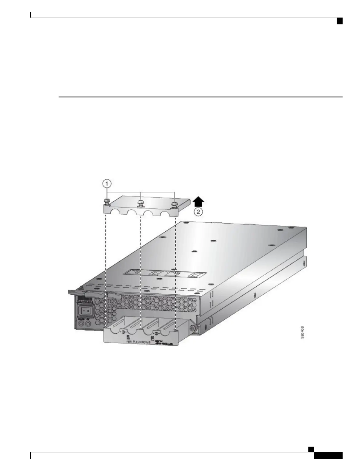
c) Use a torque screwdriver to unscrew three screws on the cover for the terminal box that is located on the front of the
power supply and lift off the cover as shown in the following figure.
The terminal box has four slots for four power terminals (ordered as negative [-], positive [+], positive [+],
and negative [-]). Each terminal has two nuts that you use to fasten a power cable to the terminal.
Note
d) Remove the two nuts from each terminal post in each slot of the terminal box.
e) Place each of the lugs for the two positive cables on the terminal posts for the positive slots (two middle slots) of the
terminal box and fasten each lug using two nuts tightened to 40 in-lb (4.5 N·m) of torque.
f) Place each of the lugs for the two negative cables on the terminal posts for the negative slots (two outside slots) of
the terminal box and fasten each lug using two nuts tightened to 40 in-lb (4.5 N·m) of torque.
g) Replace the safety cover on the terminal box and fasten it in place using its three screws.
Hardware Installation Guide for Cisco NCS 5500 Series Modular Routers
75
Install the Chassis
Connect 3kW DC Power Supply to DC Power Source