1-61
Cisco ONS 15454 DWDM Procedure Guide, R8.0
78-17704-02
Chapter 1 Install the Shelf and Common Control Cards
NTP- G11 Install an External Wire-Wrap Panel on the AEP (ANSI Only)
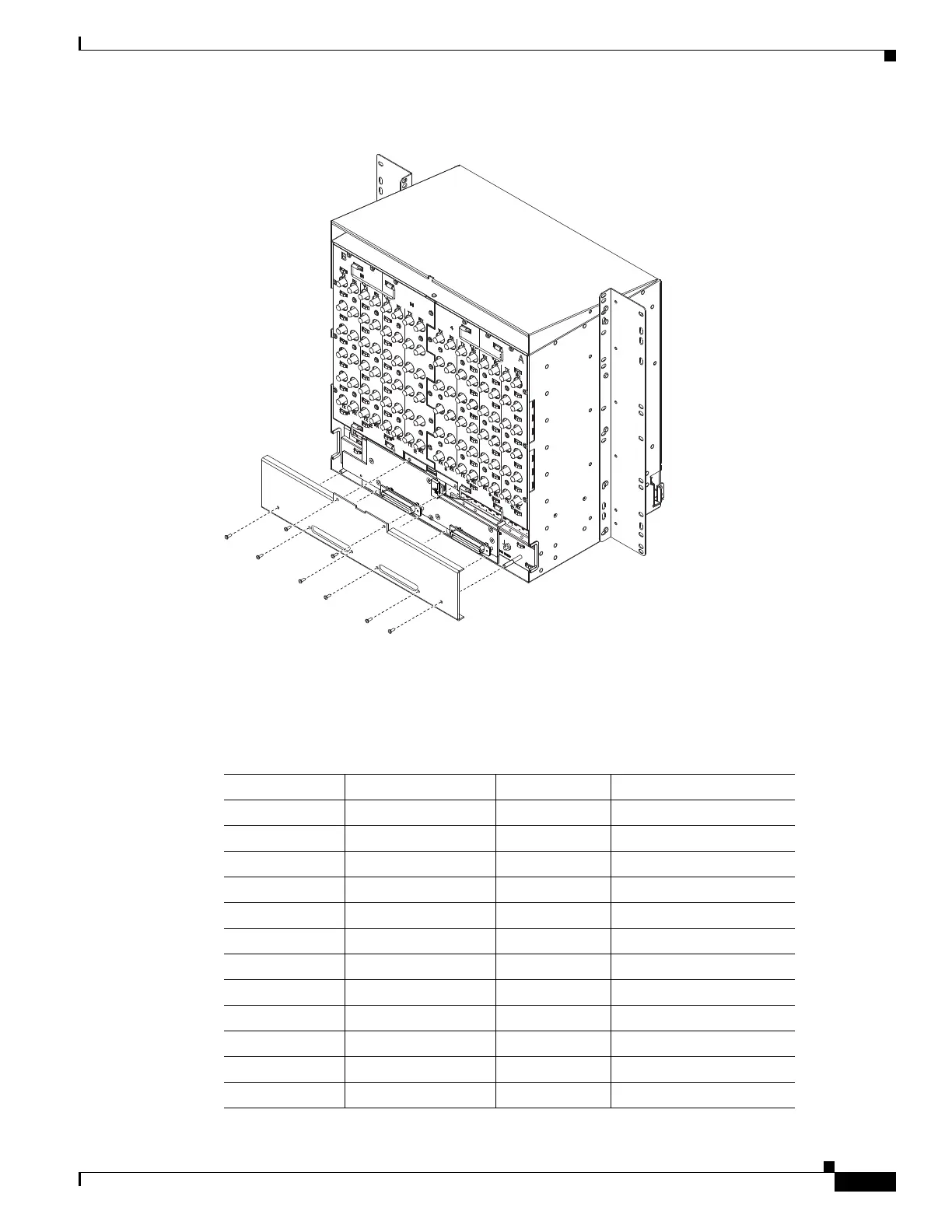
Figure 1-26 Installing the AEP Cover
Step 2
Insert and tighten the eight screws to secure the AEP cover to the AEP.
Step 3 Connect the cables from the external wire-wrap panel to the AMP Champ connectors on the AEP.
Table 1-9 lists the alarm input pin assignments.
Table 1-9 Alarm Input Pin Assignments
AMP Champ Pin Signal Name AMP Champ Pin Signal Name
1 ALARM_IN_1– 27 GND
2 GND 28 ALARM_IN_2–
3 ALARM_IN_3– 29 ALARM_IN_4–
4 ALARM_IN_5– 30 GND
5 GND 31 ALARM_IN_6–
6 ALARM_IN_7– 32 ALARM_IN_8–
7 ALARM_IN_9– 33 GND
8 GND 34 ALARM_IN_10–
9 ALARM_IN_11– 35 ALARM_IN_12–
10 ALARM_IN_13– 36 GND
11 GND 37 ALARM_IN_14–
12 ALARM_IN_15– 38 ALARM_IN_16–

 Loading...


