Procedure
Step 1 Attach an ESD wrist strap to yourself and a properly grounded point on the chassis or the rack.
Step 2 Remove the QSFP-DD transceiver module from its protective packaging.
Step 3 Check the label on the QSFP-DD transceiver module body to verify that you have the correct model for your network.
Do not remove the dust plug until you’re ready to attach the network interface cable.
Note
Step 4 Hold the QSFP-DD transceiver module by the pull-tab.
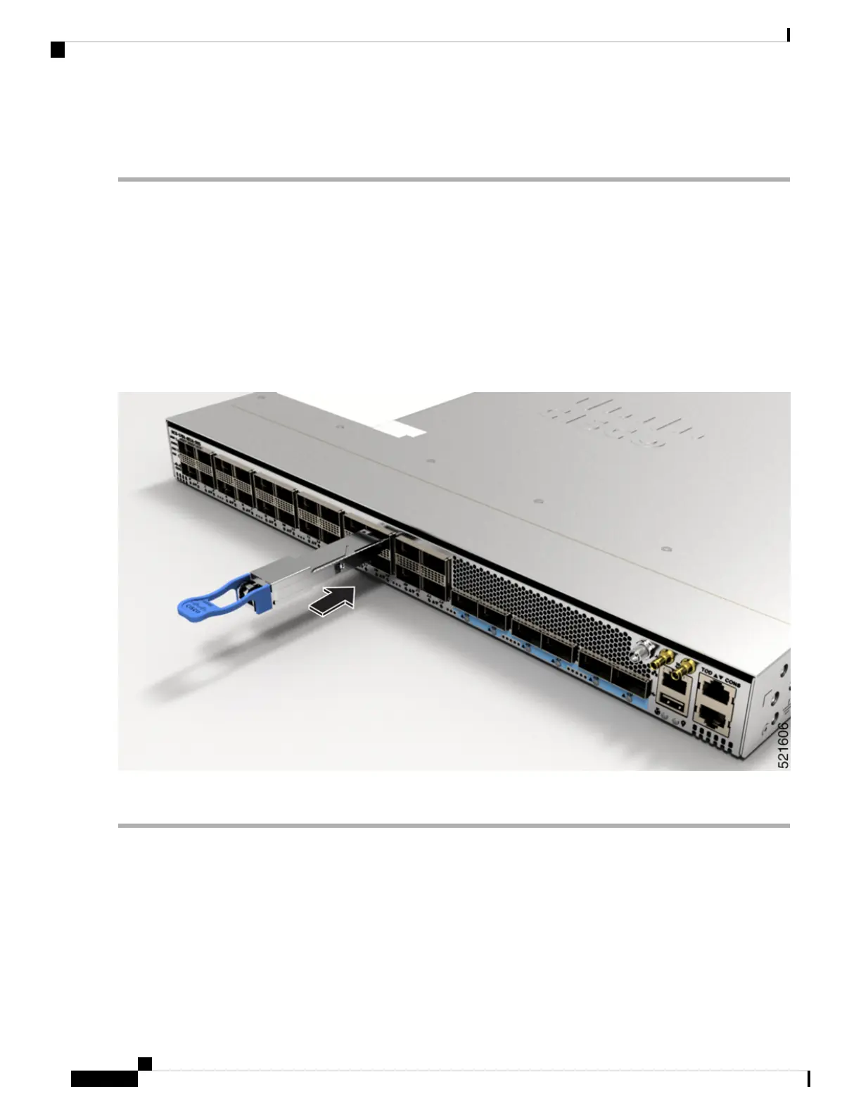
Step 5 Align the QSFP-DD transceiver module in front of the module’s transceiver socket opening and carefully slide the
transceiver into the socket until the transceiver contact with the socket electrical connector.
Figure 9: Inserting QSFP-DD Transceiver Module
Step 6 Holding the pull-tab, fully seat the transceiver in the module’s transceiver socket until it clicks.
Install and Remove QSFP+/QSFP28 Transceiver Modules
This section provides the installation, cabling, and removal instructions for the 40-Gigabit Quad Small
Form-Factor Pluggable Plus (QSFP+) and 100 Gigabit (QSFP28) transceiver modules. The modules are
hot-swappable input/output (I/O) devices that connect the system’s module port electrical circuitry with either
a copper or a fiber-optic network.
Connect Router to the Network
14
Connect Router to the Network
Install and Remove QSFP+/QSFP28 Transceiver Modules




 To Next Page