D14908.02 SX20 Administrator Guide TC6.0, JANUARY 2013. www.cisco.com — Copyright © 2012-2013 Cisco Systems, Inc. All rights reserved.
108
Cisco TelePresence SX20 Quick Set Administrator Guide
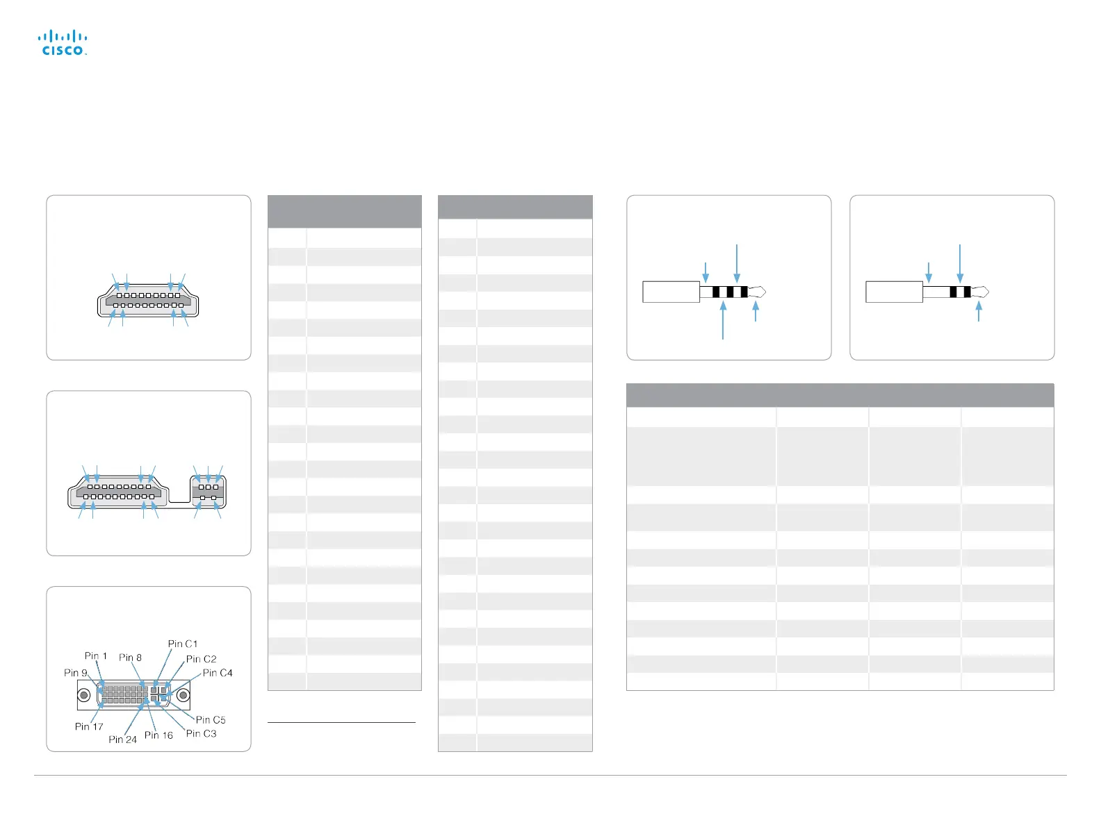
DVI-I socket pin-out
External view of socket
Pin-out schemes
This page shows the pin-out schemes for the SX20 audio, video and camera connectors.
Audio connectors (mini-jack)
Microphone Line-in Line-out
Connector pin out Tip = Hot
Ring 1 = Cold
Ring 2 = Mic. control
Shield = GND
Tip = Left channel
Ring = Right channel
Shield = GND
Tip = Left channel
Ring = Right channel
Shield = GND
Signal type Balanced Unbalanced Unbalanced
Connector (codec) Mini-jack 3.5 mm,
4-conductor
Mini-jack 3.5 mm,
3-conductor
Mini-jack 3.5 mm,
3-conductor
Input impedance 1.5 kOhm/leg 18 k Ohm N/A
Output impedance N/A N/A 100 Ohm
Maximum input level -18.3 dBu +/-2 dB 9.0 dBu +/-2 dB N/A
Maximum output level N/A N/A 8.2 dBu +/-2 dB
Phantom power 11 V +/-1 V N/A N/A
Phantom power resistor pin ”tip” 1.7 k Ohm N/A N/A
Phantom power resistor pin ”ring 1” 1.7 kO hm N/A N/A
Frequency response 20 Hz-20 kHz +/-1 dB 20 Hz-20 kHz +/-1 dB 20 Hz-20 kHz +/-1 dB
Signal to Noise Ratio -85 dB -95 dB -95 dB
3.5 mm mini-jack, 4-conductor
(microphone)
Audio – Hot
Microphone control
Audio – Cold
Ground
Camera connector pin-out
External view of socket
Pin: 2 4 16 18 22 23 24
Pin: 1 3 17 19 20 21
HDMI pin-out
External view of socket
Pin: 2 4 16 18
Pin: 1 3 17 19
3.5 mm mini-jack, 3-conductor
(line-in/line-out)
Left channel
Right channel
Ground
Camera connector and
HDMI pin-out *
Pin Assignment
1 TMDS Data 2+
2 TMDS Data 2 Shield
3 TMDS Data 2 –
4 TMDS Data 1+
5 TMDS Data 1 Shield
6 TMDS Data 1 –
7 TMDS Data 0+
8 TMDS Data 0 Shield
9 TMDS Data 0–
10 TMDS Clock+
11 TMDS Clock Shield
12 TMDS Clock-
13 CEC
14 Reserved (N.C. on device)
15 SCL
16 SDA
17 DDC / CEC Ground
18 +5 V Power (max 50 mA)
19 Hot Plug Detect
20 +12 V Power (max2 A)
21 Ground
22 RS232 Level (output)
23 Ground
24 RS232 Level (input)
Shell Ground
DVI-I socket pin-out
Pin Assignment
1 TMDS data 2-
2 TMDS data 2+
3 TMDS data 2 /4 shield
4 TMDS data 4-
5 TMDS data 4+
6 DDC clock
7 DDC data
8 Analog vertical sync
9 TMDS data 1–
10 TMDS data 1+
11 TMDS data 1 /3 shield
12 TMDS data 3-
13 TMDS data 3+
14 +5 V
15 Ground
16 Hot plug detected
17 TMDS data 0-
18 TMDS data 0+
19 TMDS data 0/5 shield
20 TMDS data 5-
21 TMDS data 5+
22 TMDS clock shield
23 TMDS clock+
24 TMDS clock-
C1 Analog red
C2 Analog green
C3 Analog blue
C4 Analog horizontal sync
C5 Analog ground
* HDMI has only pins 1 - 19; the
camera connector has pins 1 - 24.
 Loading...