Troubleshooting
Locating LEDs and components
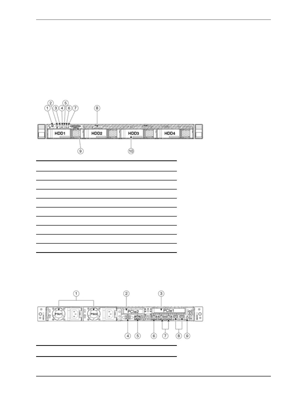
Front view
Below is an illustration of the unit's front view and a list of the LEDs and components available.
Figure 3: Front view of the CiscoTelePresence VideoCommunicationServer unit.
1 Power button/power status LED
2 Identification button/LED
3 System status LED
4 Fan status LED
5 Temperature status LED
6 Power supply status LED
7 Network link activity LED
8 Asset tag (serial number)
9 KVMconnector (for USB/VGA connection)
10 HDdrive activity/fault LED
Rear view
Below is an illustration of the unit's rear view and a list of the LEDs and components available.
Figure 4: Rear view of the CiscoTelePresence VideoCommunicationServer unit.
1 Power supplies (one for CE500)
Cisco TelePresence VCSCE500 Appliance Installation Guide (8.5) Page 12 of 16
Troubleshooting

 Loading...