6 LAN3 (not currently used)
7 LAN4 (not currently used)
8 USB port
9 USBport
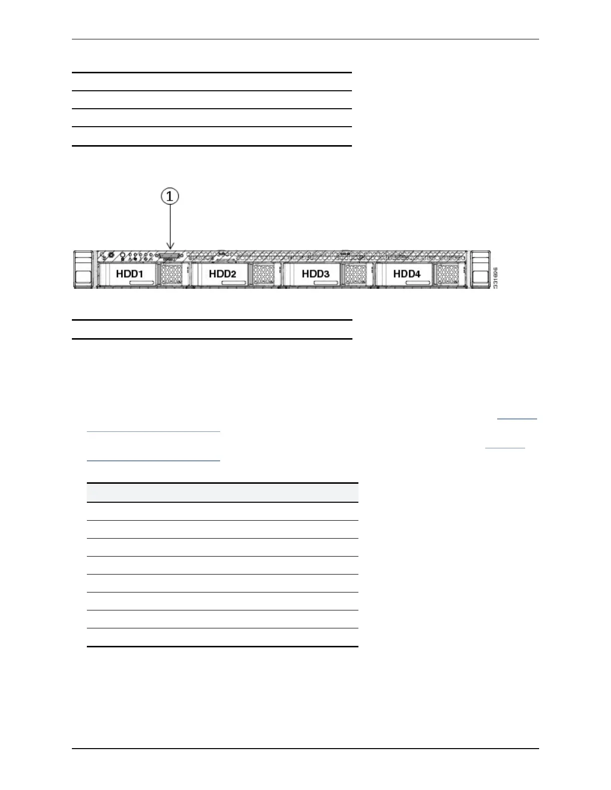
Figure 2: Front panel showing KVM connector.
The front panel port is:
1 KVMconnector
Connecting via the serial port
To connect to the CiscoVCS via the serial port:
1. Connect the Ethernet LAN cable from the LAN 1 port on the rear of the unit to your network.
The LAN 1 port is the left-hand port of the dual port adapter on the rear panel of the unit (shown in Figure 1:
Rear panel showing ports. [p.7]).
2. Connect a serial cable from the serial port on the rear of the unit to the serial port on a PC (see Figure 1:
Rear panel showing ports. [p.7]).
The serial cable used must be a cross-over cable. The pin assignment for the serial cable is:
Male RJ45 pin Female DB9 pin
1 8
2 6
3 TXD 2
4 GND 5
5 GND 5
6 RXD 3
7 4
8 7
Note:if there is no DB9 port on your PC, a DB9 to USBserial port adapter is required.
3. Start a terminal emulator program (for example PuTTY) on the PC and configure it to use the PC’s serial
port as follows:
Cisco TelePresence VCSCE500 Appliance Installation Guide (8.5) Page 8 of 16
Configuring

 Loading...