D-15
Cisco UCS C240 M4 Server Installation and Service Guide
OL-32474-01
Appendix D GPU Card Installation
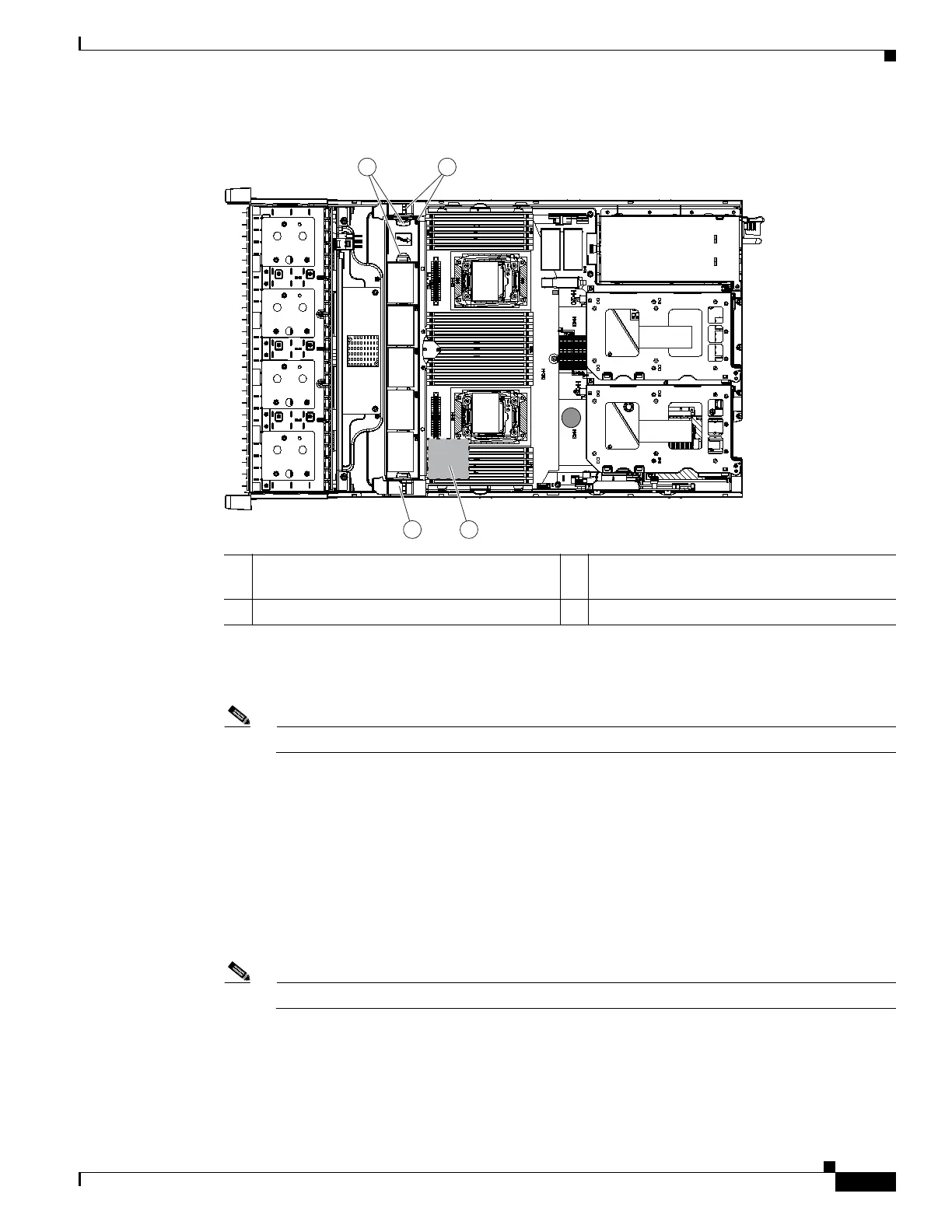
Figure D-6 Fan Cage and Fan Modules
Step 9 Remove the existing heatsink from each CPU.
a. Use a Number 2 Phillips-head screwdriver to loosen the four captive screws that secure the heatsink.
Note Alternate loosening each screw evenly to avoid damaging the heatsink or CPU.
b. Lift the heatsink off of the CPU and set it aside.
Step 10 Use the heatsink cleaning kit that comes with the conversion kit to clean the existing thermal grease from
the top surface of each CPU.
Step 11 Install the low-profile replacement heatsinks that come with the conversion kit:
a. Remove the protective tape from the pre-applied pad of thermal grease that is on the underside of
the new heatsink.
b. Align the four heatsink captive screws with the motherboard standoffs, and then use a Number 2
Phillips-head screwdriver to tighten the captive screws evenly.
Note Alternate tightening each screw evenly to avoid damaging the heatsink or CPU.
Step 12 Set the base of the replacement air baffle into the server (see Figure D-7).
1 Finger latches (on each fan module) 3 SuperCap power module position on
removable air baffle (air baffle not shown)
2 Fan cage plastic locking-levers
FAN 05
FAN 04
FAN 0 3
FAN 0 2
FAN 01
CPU 1
CPU 2
SD1
SD2
Riser 2
Riser 1
305091
1 2
2 3

 Loading...


