3-4
Cisco UCS C240 M4 Server Installation and Service Guide
OL-32474-01
Chapter 3 Maintaining the Server
Status LEDs and Buttons
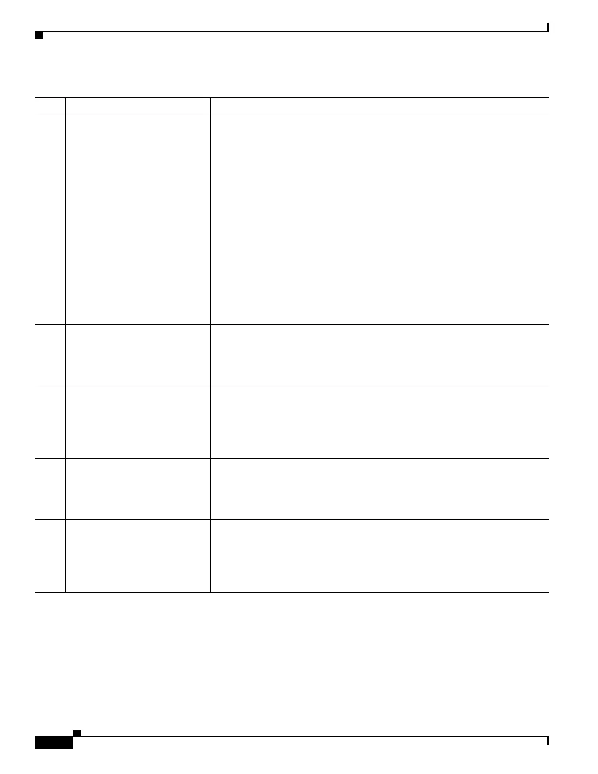
5 System status • Green—The server is running in a normal operating condition.
• Green, blinking—The server is performing system initialization and memory
check.
• Amber, steady—The server is in a degraded operational state. For example:
–
Power supply redundancy is lost.
–
CPUs are mismatched.
–
At least one CPU is faulty.
–
At least one DIMM is faulty.
–
At least one drive in a RAID configuration failed.
• Amber, blinking—The server is in a critical fault state. For example:
–
Boot failed.
–
Fatal CPU and/or bus error is detected.
–
Server is in an over-temperature condition.
6 Fan status
• Green—All fan modules are operating properly.
• Amber, steady—One or more fan modules breached the critical threshold.
• Amber, blinking—One or more fan modules breached the non-recoverable
threshold.
7 Temperature status
• Green—The server is operating at normal temperature.
• Amber, steady—One or more temperature sensors breached the critical
threshold.
• Amber, blinking—One or more temperature sensors breached the
non-recoverable threshold.
8 Power supply status
• Green—All power supplies are operating normally.
• Amber, steady—One or more power supplies are in a degraded operational
state.
• Amber, blinking—One or more power supplies are in a critical fault state.
9 Network link activity
• Off—The Ethernet link is idle.
• Green—One or more Ethernet LOM ports are link-active, but there is no
activity.
• Green, blinking—One or more Ethernet LOM ports are link-active, with
activity.
Table 3-1 Front Panel LEDs, Definitions of States (continued)
LED Name State
 Loading...


