E-16
Cisco UCS S3260 Storage Server Chassis Installation and Service Guide
Appendix E Upgrading to Cisco UCS S3260 System With S3260 M5 Server Nodes
Installing a Second Server Node or SIOC to the S3260 System With M5 Server Node
Step 12 Configure the management, CMC, and BMC IP addresses for the system.
Note If you use a DHCP server and you already have QSFP cables attached to the SIOC, the management IP
address and network settings are already filled in. If you disable DHCP, you must set your own static
management IP address and network settings.
Step 13 This step only for setting static IPs (DHCP disabled)—Set the CMC and BMC internal IP addresses
by using the Cisco IMC interface, as described in Setting Static CMC and BMC Internal IP Addresses,
page 2-18.
Step 14 Use the Cisco IMC (GUI or CLI) to define drive zoning, which maps the NVMe SSD drives in the
Version 03 SIOC(s) to individual server nodes:
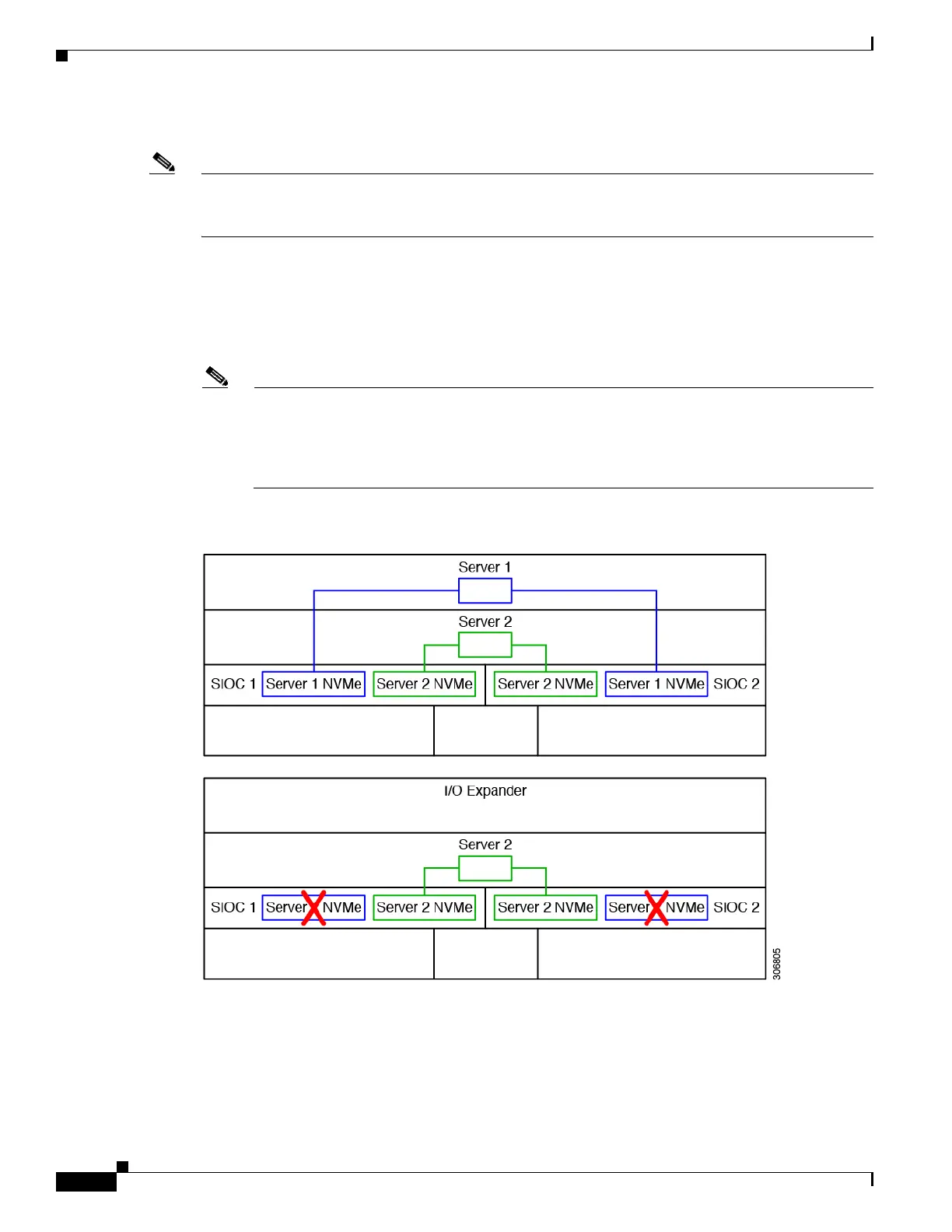
Note An NVMe SSD in the SIOC slot that is labeled SERVER 1 NVME is supported only by a server
node in upper server bay 1. An NVMe SSD in the SIOC slot that is labeled SERVER 2 NVME is
supported only by a server node in lower server bay 2. Figure E-1 shows examples of the
connectivity. In the lower view, the system has an I/O expander populated in server bay 1 and so
the SERVER 1 NVME slots cannot be used.
Figure E-1 NVMe SSD Connectivity in Version 03 SIOC (UCS-S3260-PCISIOC)

 Loading...


