3-47
Cisco UCS S3260 Storage Server Chassis Installation and Service Guide
Chapter 3 Maintaining the System
Installing or Replacing System Components
Replacing an S3260 Chassis
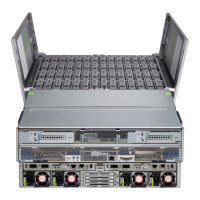
This procedure is for replacing an S3260 chassis and transferring all components to the new chassis.
Step 1 Export the component configurations (CMC, BMC, VIC adapters) and save them to a local computer
using the import-export command mode.
Refer to the Cisco UCS Integrated Management Controller CLI Configuration Guide for S3260 Storage
Servers. See the chapter, Server Utilities and the section, Exporting and Importing the Cisco IMC and
BMC Configuration.
Step 2 Perform a graceful shutdown of all server nodes.
See Shutting Down an Individual Server Node, page 3-10 for more information.
Step 3 Disconnect all power cables from all power supplies to fully remove power from the chassis.
Step 4 Remove each server node and install each to the same bay position in the new chassis.
If a server node has an I/O expander attached, move the node and expander attached together.
See the service note for your server node version for more information: Server Node Service Notes.
Step 5 If the system has a disk expansion tray in place of a server node, remove it with its disks in place and
install the tray with disks to the same bay position in the new chassis.
See Replacing a Disk Expansion Tray, page 3-27 for more information.
Step 6 Remove each SIOC and install each to the same bay position in the new chassis.
See Replacing a System I/O Controller (SIOC), page 3-28 for more information.
Step 7 Remove each rear-panel boot SSD and install each to the same bay position in the new chassis.
See Replacing SAS/SATA Solid State Drives in the Rear Panel Bays, page 3-23 for more information.
Step 8 Remove each power supply and install each to the same bay position in the new chassis.
See Replacing a Power Supply, page 3-33 for more information.
Step 9 Open the main chassis top cover on the old and new chassis.
See Opening the Main Chassis Top Covers, page 3-12 for more information.
Step 10 Remove each top-loading hard drive and install each to the same bay position in the new chassis.
See Replacing HDDs or SSDs in the Internal Drive Compartment, page 3-18 for more information.
Step 11 Open the fan compartment cover on the old and new chassis.
Step 12 Remove each cooling fan and install each to the same bay position in the new chassis.
See Replacing Fan Modules, page 3-25 for more information.
Step 13 If you have not done so already, remove the empty chassis from your rack.
Step 14 Close all covers on the new chassis.
Step 15 Install the new chassis to your rack.
Caution This system weighs approximately 190 pounds (86 kilograms) when fully loaded with components. We
recommend that you use a mechanical lift when lifting the system. Attempting this procedure without a
lift could result in personal injury or equipment damage. Although not required, consider temporarily
removing components such as hard drives while you move the system.
See Installing the System in a Rack, page 2-5 for instructions.

 Loading...