14
Connecting the Voice Cable
Table 2 describes the voice cable and connection.
9 Powering On the Voice Gateway
Before You Begin
Before you power on your Cisco VG202, Cisco VG202XM, Cisco VG204, or Cisco VG204XM voice gateway, ensure that it
meets these requirements:
• The chassis is securely mounted.
• The power and interface cables are connected.
Procedure
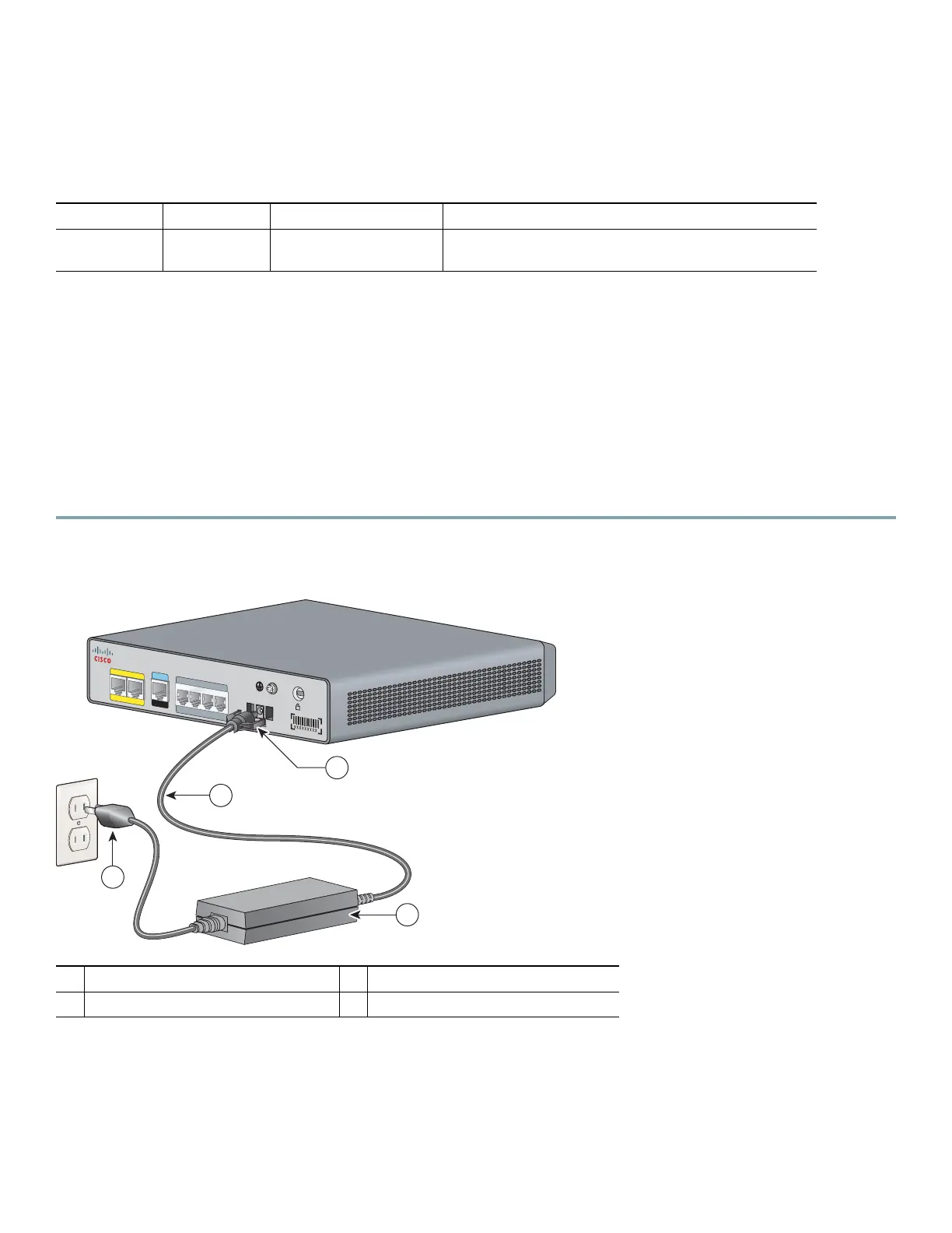
Step 1 Connect your voice gateway DC cable as shown in Figure 10.
Figure 10 Connecting the External Power Supply to Your Voice Gateway
Step 2 Plug the AC plug into a wall outlet.
The green OK LED lights up.
The system displays the following message at the end of the bootup messages:
--- System Configuration Dialog ---
Would you like to enter the initial configuration dialog? [yes/no]:
Table 2 Voice Cable and Connection
Port/Interface Color or Type Connected To Cable
Analog
voice/FXS
RJ-11 Distribution panel or
telephone
RJ-11-to-RJ-11 straight-through cable (not included)
1
DC plug
2
Power cord
3
Power adapter
4
AC plug
VG204
12V D
C S
A
CO
N
SOL
E
AU
X
FastEthernet
0/1
0/0
FXS
0/1
0/
20/3
0/0
272269
1
2
4
3