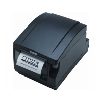
CT-S651 Series Service Manual
- 22 -
14. Disassembling “LEVER R & L, CUTTER RELEASE-02”
Detach “SPRING, LEVER CUTTER-02” from the hooks at “SA, FRAME MAIN” and “LEVER R, CUTTER
RELEASE-02”. Turn “LEVER R, CUTTER RELEASE -02” toward you and remove it from the shaft at
“SA, FRAME MAIN”. Remove “LEVER L, CUTTER RELEASE-02” in the same way.
15. Disassembling “PLATE, COVER LOCK LEVER-02”
Remove “SPRING, COVER OPEN LEVER-02” from the hooks at “LEVER R, COVER LOCK-02” and
“SA, MAIN FRAME”. Remove four “SCREW, PHT (ST), M3.0 × 6” that fasten “LEVER, R & L COVER
LOCK-02” and “PLATE, COVER LOCK LEVER-02”.
16. Disassembling “LEVER R & L COVER LOCK-02”
Turn “LEVER R, COVER LOCK-02” until the hook is aligned with the hole at “SA, FRAME MAIN”, and
remove “LEVER R, COVER LOCK-02” along the hole. Remove “LEVER L, COVER LOCK-02” in the
same way.
SCREW, PHT (ST), M3.0 × 6
SPRING, COVER OPEN LEVER-02
PLATE, COVER LOCK LEVER-02
LEVER R, COVER LOCK-02
LEVER L, COVER LOCK-02
LEVER R, CUTTER RELEASE-02

 Loading...