OPERATION No MA. 390-O :
ChrckinR thr bydraalir co’mponcnts on the u&i&
f Manual stcprine r~ebidos t
Op. MA. 390.0
1
CHECKING’THE HYDRAULIC COMPONENTS
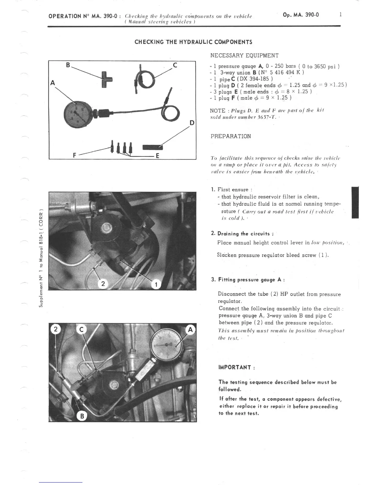
NECESSARY EQUIPMENT
- 1 pressure gauge
A,
0 - 250
bars ( 0 to 3650
psi
)
_ 1 3-way union B (No 5 416 494 K 1
- 1 pipeC (DX 394-185 ) ..
- 1 plug D ( 2 female ends 4 1.25 and 6 9 X1.25) = =
- 3
plugs
E (mole
ends : r$ 8 X 1.25 ) =
- 1 plug
F (
mole 4 = 9 x 1.25 1
NOTE
: Plugs D, E md
F are part 01 fhe kit
sold snder number 3657-T.
PREPARATION
1.
First ensure :
- that hydraulic reservoir filter is clean.
- that hydraulic fluid is ot normal running tempe-
rature ( Carry 0~1 a road lent first i/ vt4icie
is
mid ). 8
2. Draining the circuits :
Place manual height control lever in ion,
posirios,
Slacken pressure regulator bleed screw ( 1 ).
3. Fitting pressure gouge A :
Disconnect the tube (2) HP outlet from pressure
regulator.
Connect the following assembly into the circuit :
pressure gaoge A, 3way union B and pipe C
between pipe ( 2) and the pressure regulator.
This ass~nzhly mrtst remain in positioa /brougbo~~l
the test.
IMPORTANT :
The testing kquance described below must be
followed.
If after the test, a component appears defective,
either replace it or repair it before proceeding
to the next test.