.
DEVICE FOR HEATING THE INLET AIR
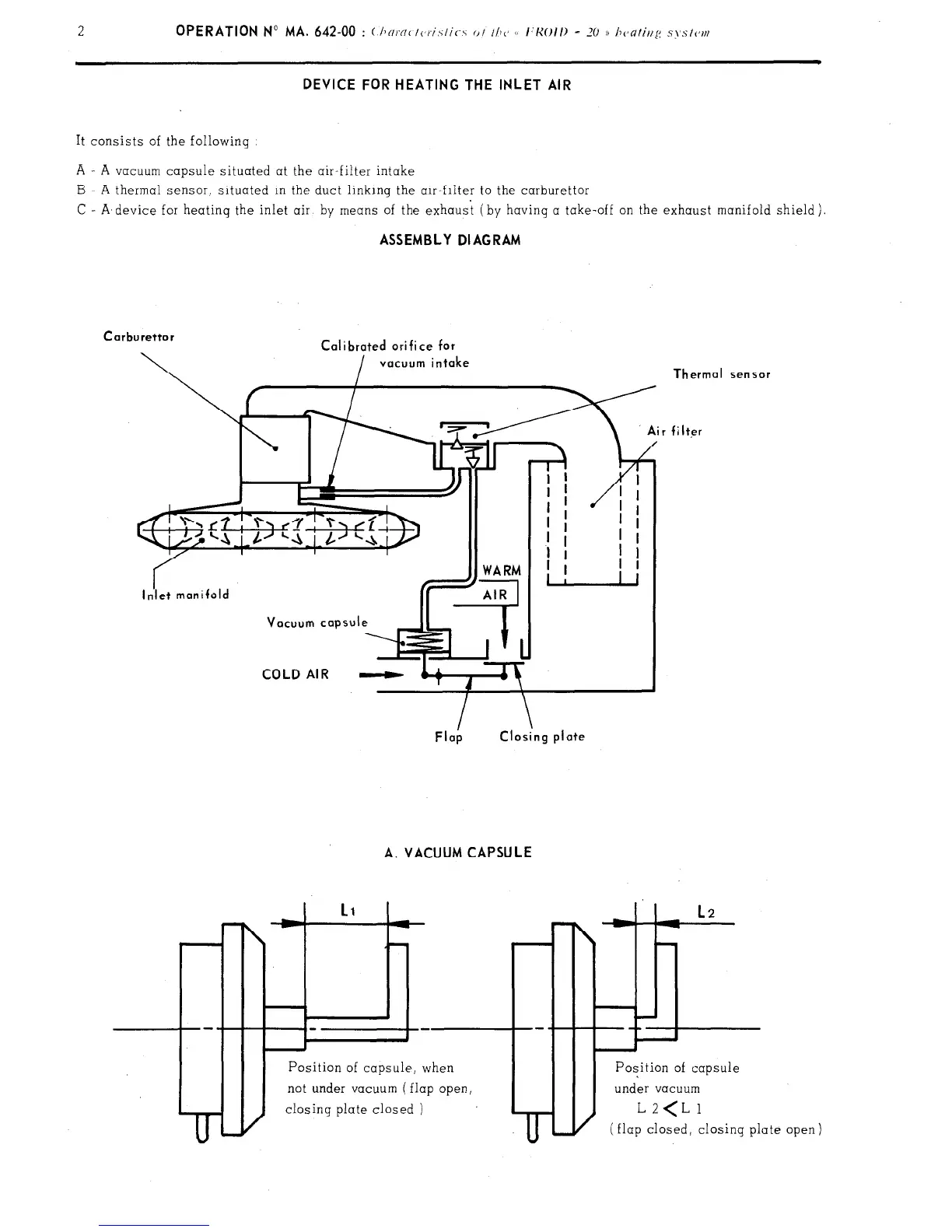
It consists of the following
A
-
A
vacuum capsule situated at the air-filter intake
B A thermal sensor, situated in the duct linking the air-filter to the carburettor
C - A,device for heatinq the inlet air by means of the exhaust (by having a take-off on the exhaust manifold shield).
ASSEMBLY DIAGRAM
Carburettor
Calibrated ori fi ce for
vacuum intake
COLD AIR -
A. VACUUM CAPSULE
II
I
I
t
I
Position of capsule, when
not under vacuum ( flap open,
closing plate closed )
I
m-t
L2
L-H ii
---+-
Thermal
sensor
filter
Position of capsule
under vacuum
(flap closed, closing
plate
open 1