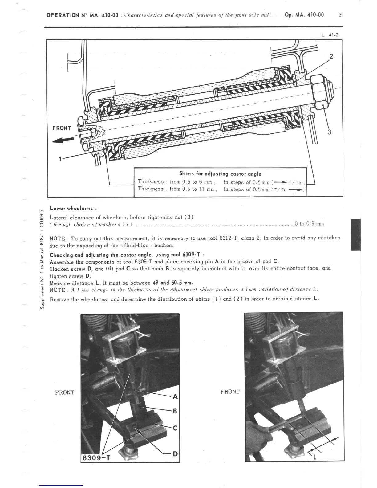
Shims for adjusting castor angle
Thickness from 0.5 to 6 mm ,
in steps of 0.5mm (-
- Lower wheelorms :
E Lateral cleoronce of wheelarm. before tightening nut (3 1
z ( fbmugh rhoicr o/ wnshr~r I I u I ,..................,.,............................,..,..,.,........................,....,...... 0
to
0.9 mm
2 NOTE To carry out this measurement, it is necessary to use tool 6312-T. class 2. in order to ovoid any mistakes
t due to the expanding of the G fluid-bloc n bushes.
g Checking and adjusting the castor angle, using tool 6309-T :
s Assemble the components of tool 6309-T and place checking pin
A
in the groove of pod C.
2 Slacken screw
D,
and tilt pad C so that bush B is squarely in contact with it, over its entire contact face. and
f tighten screw
D.
; Measure distance
L.
It must be between 49
and 50.5 mm.
: NOTE A I mm rhaug~~ ia the Ihirknrss o//he adjr~s/mw/ shims produc-~s a Imm r~ariatim oi rlislmc~ L.
Remove the wheelarms, and determine the distribution of shims ( 1) and ( 2 ) in order to obtain distance
L.
FRONT
FRON T