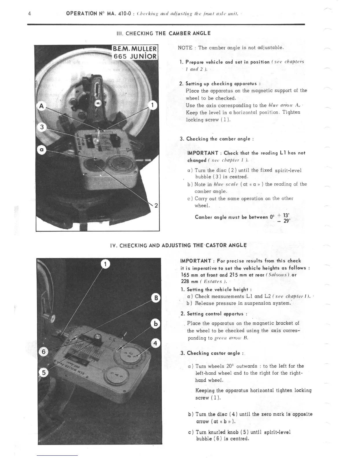
III. CHECKING THE CAMBER ANGLE
NOTE : The camber angle is not adjustable.
1. Prepare vehicle and set in position f src chapfrrs
I and 2 ).
2. Setting up checking apparatus :
Place the apparatus on the magnetic support of the
wheel to be checked.
Use the axis corresponding to the blue mmu A..
Keep the level in a horizontal position. Tighten
locking screw ( 1).
3. Checking the comber angle :
IMPORTANT : Check that the reading Ll has not
changed ( SC<’ rhnprcr I ).
a) Turn the disc (2 ) until the fixed spirit-level
bubble (3 1 is centred.
b)
Note in blur scnle (at o a n ) the reading of the
comber rmqle.
c ) Carry out the same operation on the other
wheel.
Comber angle must be between 0’ + 13’
- 29’
IV. CHECKING AND ADJUSTING THE,CASTOR ANGLE
IMPORTANT : For precise results from this check
it is imperative to set the vehicle heights as follows :
165 mm a+ front and 215 mm at rear f Salooss) or
228
mm ( Esfafes ).
1. Setting the vehicle height :
a) Check measurements Ll and L2 f see chapter I ).
b ) Release pressure in suspension system.
2.
Setting control opportus :
3.
Checking castor angle :
Place the apparatus on the magnetic bracket of
the wheel to be checked using the axis corres-
ponding to grren (ITTOII’ H.
a)
Turn
wheels 20’ outwards : to the left for the
left-hand wheel and to the right for the right-
hand wheel.
Keeping the apparatus horizontal tighten locking
screw ( 1).
b) Turn the disc ( 4) until the zaro mark is opposite
arrow (at I( b n 1.
c) Turn knurled knob ( 5) until spirit-level
bubble (6) is centred.