B. THERMAL SENSOR
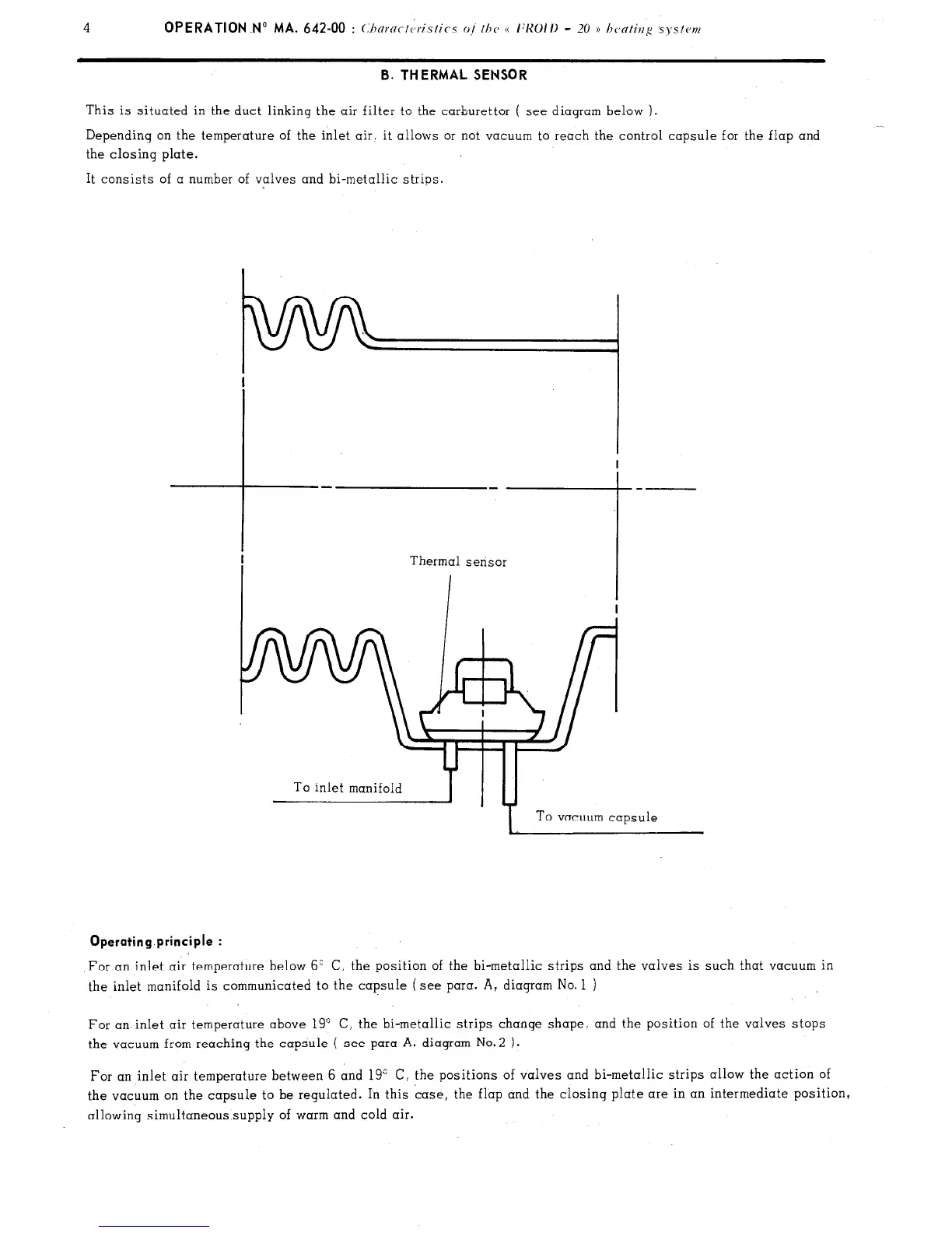
This is situated in the duct linking the air filter to the carburettor ( see diagram below ).
__
Depending on the temperature of the inlet air. it allows or not vacuum to reach the control capsule for the flap and
the closing plate.
It consists of a number of valves and bi-metallic strips.
To inlet manifoldb-yTu-4
I
To vacuum capsule
Operating principle :
For an inlet air temperature below 6’
C, the position of the bi-metallic strips and the valves is such that vacuum in
the inlet manifold is communicated to the capsule (see para. A, diagram No. 1 )
For an inlet air temperature above 19” C, the bi-metallic strips change shape. and the position of the valves stops
the vacuum from reaching the capsule ( see para A. diagram No.2 ).
For an inlet air temperature between 6 and 19” C, the positions of valves and bi-metallic strips allow the action of
the vacuum on the capsule to be regulated. In this case, the flap and the closing plate are in an intermediate position,
allowing simultaneous supply of warm and cold air.
 Loading...


