2
OPERATION No MA. 142-00 :Cbaracteris/ics and special j~,attlr~s o/the
carhrrre~~or
7 6
8
9
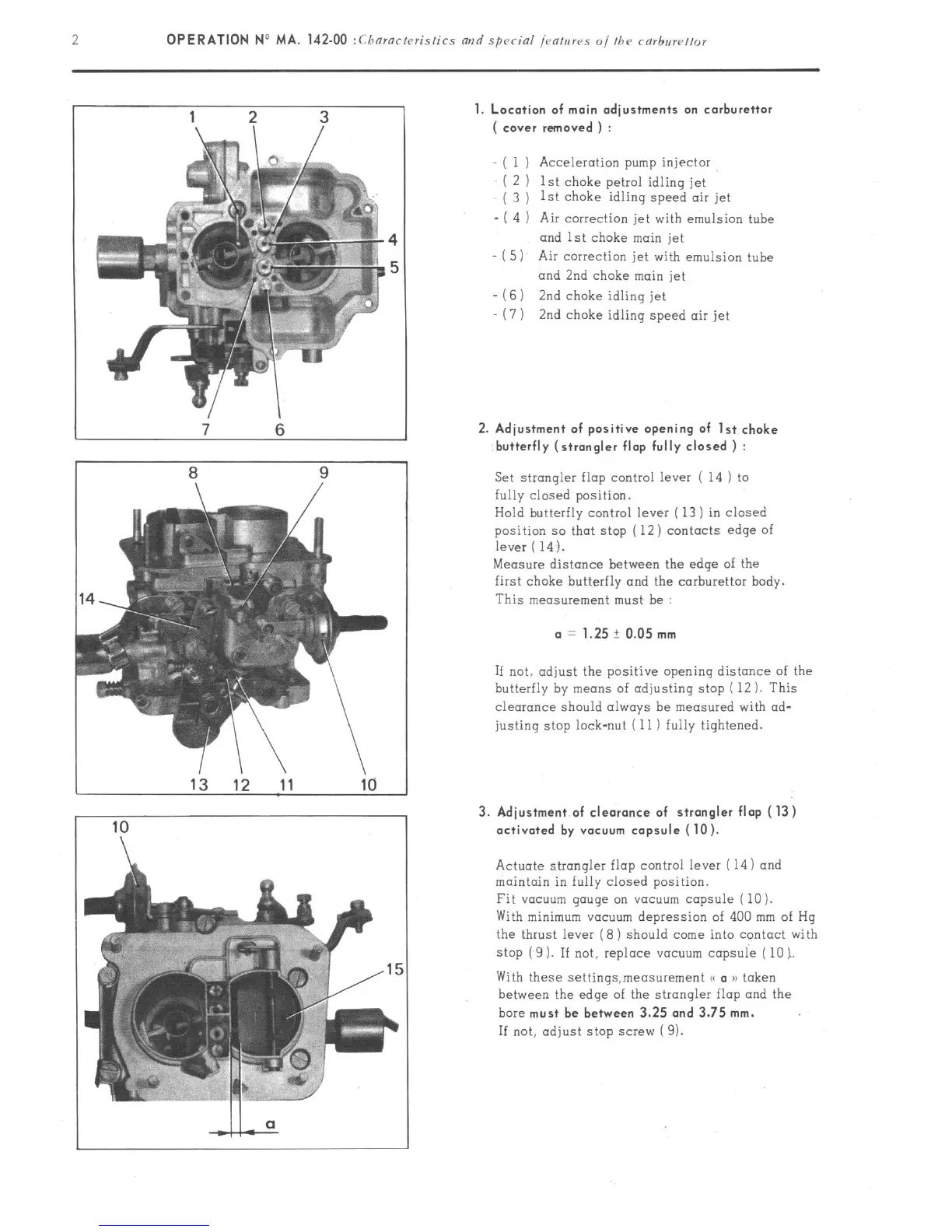
1 ) Acceleration pump injector
2 ) 1st choke petrol idling jet
3 ) 1st choke idling speed air jet
4 ) Air correction jet with emulsion tube
and 1st choke main jet
-(5
) Air correction jet with emulsion
tube
and 2nd choke main jet
-16
) 2nd choke idling jet
-(7
) 2nd choke idling speed air jet
1. Location of main adjustments on carburettor
( cover removed ) :
2. Adjustment of positive opening of 1st choke
butterfly (strangler flap fully closed ) :
Set strangler flap control lever ( 14 ) to
fully closed position.
Hold butterfly control lever ( 13 ) in closed
position so that stop (12) contacts edge of
lever ( 14 ).
Measure distance between the edge of the
first choke butterfly and the carburettor body.
This measurement must he :
a = 1.25? 0.05 mm
If not, adjust the positive opening distance of the
butterfly by means of adjusting stop ( 12 ). This
clearance should always he measured with ad-
justing stop lock-nut ( 11 ) fully tightened.
3. Adjustment of clearonce of strangler flap (13)
activated by vacuum capsule (10).
Actuate strangler flap control lever ( 14) and
maintain in fully closed position.
Fit VCICUUII~ gouge on V~CUUIII capsule ( 10 ).
With minimum v(~cu”m depression of 400 mm of Hq
the thrust lever (8 ) should come into contact with
stop (9 ). If not, replace YClCUUrn capsule ( 10 ).
With these setti”gs,meosureme”t (G a aa taken
between the edge of the strangler flap and the
bore must
be between 3.25 and 3.75 mm.
If not, adjust stop screw (3).