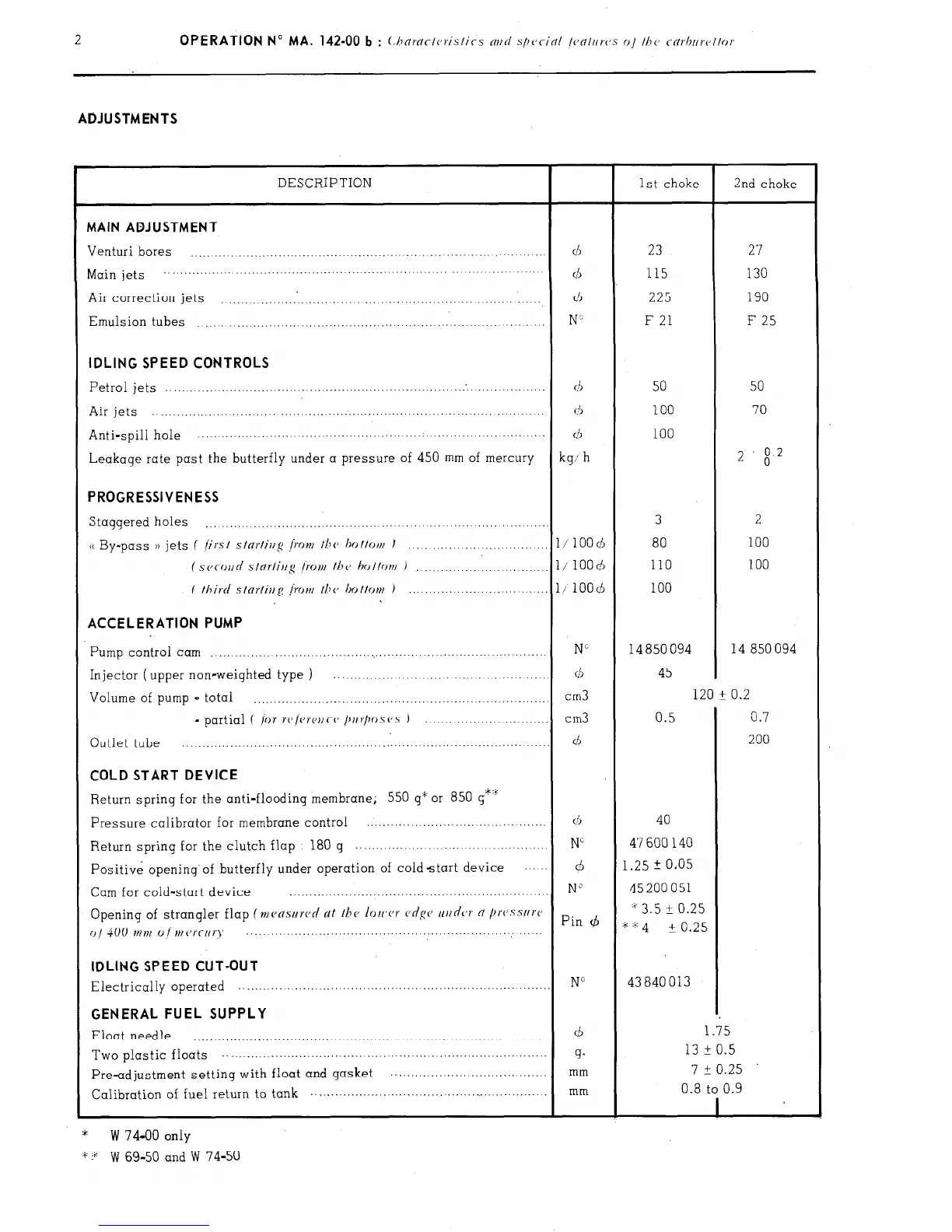
ADJUSTMENTS
DESCRIPTION
1st choke
2nd choke
MAIN ADJUSTMENT
Venturi bores
...................................................................................
d
23
27
Main jets
................. ...........................
... ................. ... ....... ...............
cl5 115 130
Air correction jets ..............................................................
d 225 190
Emulsion tubes
...............................................................
......
N’
F 21
F 25
IDLING SPEED CONTROLS
Petrol jets
.......................................................................................
d
50 50
Air jets .....................................................................................
(3
100 70
Anti-spill hole
............... ..............................................
....... ........
d 100
Leakage rate past the butterfly under a pressure of 450 mm of mercury
kg; h
2
$2
PROGRESSIVENESS
Staggered holes 3
2
...............................................................................
u By-pass )) jets (
/irst stnrtiug /row the
ho ttott/ J
100 ............................ 1 / 100 cb 80
( SC~COII~ slnrlirrg I.0Nf the bottom )
......................
l/ 1OOd 110 100
( third stnrfiug [row the bottov~ )
...........................
l/100($
100
ACCELERATION PUMP
Pump control cam N”
14 850 094 14 850 094
...............................................................................
Injector ( upper non-weighted type ) ............................................
d 45
Volume of pump - total
cm3
120 -t 0.2
.......................................................................
- partial ( /or r(‘/vre)~Co /~IIr/wS(‘S )
................... ...........
cm3 0.5
0.7
Outlet tube
200 ................................................. ....... ...........
............... ...
d
COLD START DEVICE
Return spring for the anti-flooding membrane; 550 g” or 850 g*‘i;
Pressure calibrator for membrane control
...........................................
(1, 40
Return
spring
for the clutch flap
180 g ...............................................
Ni
47 600 140
Positive opening’of butterfly under operation of coldstart device
.... d
1.25 2 0.05
Cam for cold-start device
N”
45 200 051
..............................................................
Opening of strangler flap (mensllrcd
dt
the loIc,cr c,dgc’ ur/dcJT 0 /lI’(‘.sSlI)‘C
* 3.5 i 0.25
() j 4(j(J tr ,),, (J ,,, (Jr(-[,q
Pin (b
““4 -t 0.25
..... ... .....................................................
... ......
IDLING SPEED CUT-OUT
Electrically operated NG 43840013 .............................................................................
GENERAL FUEL SUPPLY
Float needle
d
1.35
..................................................................................
Two plastic floats
13 F 0.5 ...................................
............... .............................
g.
7 t 0.25
Pre-adjustment setting with float and gasket
...............................
....... mm
Calibration of fuel return to tank
.................................
......................... mm 0.8 to 0.9
1
*
W 74-00 only
* + W 69-50 and W 74-50
.