Hydraulic / Electric System LINER TIC
4-2 10/04
1.0 LINER 3000
1.1 Hydraulic System
1.1.1 Hydraulic circuit
diagram
M 1 Circulation blocking solenoid valve (master valve)
M 2 Lower chassis solenoid valve
M 3 Raise chassis solenoid valve
M 4 Lower front rotors solenoid valve
M 5 Raise front rotors solenoid valve
M 6 Front rotors wider solenoid valve
M 7 Front rotors narrower solenoid valve
M 8 Raise rear rotors solenoid valve
M 9 Lower rear rotors solenoid valve
M 10 Lower rear rotors solenoid valve
11 Two-way flow divider
12 Raise/lower chassis hydraulic cylinder
13 Raise/lower front rotors hydraulic cylinder
14 Swath width front narrower/wider hydraulic cylinder
15 Raise/lower rear rotors hydraulic cylinder
16 Quick release coupling on tractor P (pressure)
17 Quick release coupling on tractor T (pressureless return line)
19 Lock-up valve unit
20 One-way restrictor valve (drop rate restrictor)
21 Valve block, complete
22 Valve block, complete
23 Shut-off tap
24 High-pressure filter
X John Deere screw (constant-pressure hydraulic system) via screw on the
solenoid.
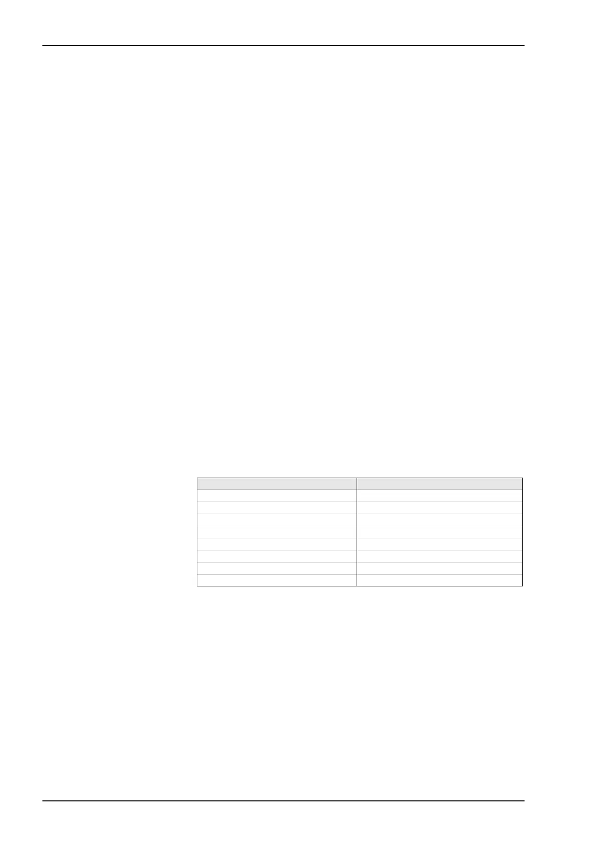
1.1.2 Function - valve
assignment
Function Valve
Raise front rotors 1 + 5
Lower front rotors 1 + 4
Raise rear rotors 1+ 8
Lower rear rotors 1+ 9 + 10
Raise chassis 1 + 3
Lower chassis 1 + 2
Increase working width 1 + 6
Decrease working width 1 + 7
 Loading...