•
Montaje
fijo
(Autom6viles
TOYOTA,
NISSAN,
Y
otros
provistos
de
normas
ISO/DIN)
Esta
unidad
ha
sido
disenada
para
instalarse
de
forma
fija
en el
tablero
de
instrumentos.
Si el
autom6vil
dispone
de
una
radio instal
ada
en fabrica, instale
la
unidad
fuente
con las
piezas
y los tornillos
marcados
con
(*)
en la Figura 7.
Si el autom6vil
no
dispone
de
una
radio instalada en fabrica, adquiera
un
juego
de
instalaci6n
para
instalar la unidad fuente
de
acuerdo con
el procedimiento siguiente.
Doble
de
instalar
esta
unidad
en
vehfculos
TOYOTA,
NISSAN,
Y
otoros
equipados
con
ISO/DIN,
extraiga
el reten
siguiendo
los pro-
cedimientos indicados a continuaci6n.
ISO/DIN)
uno
installation fixe
dans
Ie
de
auto-radio installe I'usine,
et les ecrous
marquees
de
d'un auto-radio installe al'usine
se
d'itlstallciticm
pur
installer rappareil pilote
avec
la
Montc:lge
fixe
NISSAN
et
autres
vehicules
1.
Bend
the
stopper
from the source unit. (Figure 5, 6)
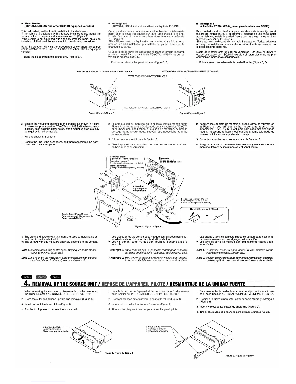
• Fixed
Mount
(TOYOTA, NISSAN
and
other
ISO/DIN
equipped
vehicles)
This
unit is designed
for
fixed installation in
the
dashboard.
If
the
vehicle
is
equipped
with
a
factory-installed
radio,
install
the
source unit with
the
parts
and
screws
marked
(*)
(Figure 7).
If
the
vehicle
is
not
equipped
with a factory-installed radio, obtain an
installation kit to install
the
source unit in
the
following procedure.
Bend
the
stopper
following
the
procedures
below
when
this
source
unit is installed to the TOYOTA,
NISSAN
and
other
ISO/DIN equipped
vehicles.
1.
Coubez
la butee
de
I'appareil source. (Figure 5, 6)
1. Doble el reten procedente
de
la unidad fuente. (Figura 5, 6)
BEFORE
BEND/AVANT
LA
COURBUREIANTES
DE
DOBLAR
AFTER
BEND/APRES
LA
COURBUREIDESPUES
DE
DOBLAR
STOPPERfTOURNEVIS/DESTORNILLAODR
SOURCE UNIT/APPAREIL PILOTE/UNlOAD FUENTE
Figure 5/Figure 5/Figura 5
Figure 6/Figure 6/Figura 6
3,
Cabler
comme
montre
dans
la Section
8,
4.
Asegure
la unidad al tablero
de
instrumentos, y
despues
vuelva
a
montar
el tablero
de
instrumentos y el panel central.
2.
Asegure
los
soportes
de
montaje
al
chasis
como
se
muestra
en
la
Figura
7.
Los
orificios
ya
han
sido
taladrados
en
los
autom6viles
TOYOTA
y NISSAN,
pero
para
otros
modelos
puede
resultar
necesario
realizar
modificaciones,
como
taladrado
de
nuevos orificios en los soportes
de
montaje.
3.
Conecte
los cables
como
se
muestra
en la Secci6n 8.
comme
montra
pn:}=u~SC{)U~H3S
pour
les vehicules
...
r
...
,
....
rr"
...
A
mC)dl1'ICcitloln
de
comme
Ie
etre
pour
les
dans
Ie
tableau de bord puis remonter
Ie
tableau
panneau central.
2.
4.
Secure
the
unit in
the
dashboard,
and
then reassemble
the
dash-
board
and
the
center panel.
2.
Secure
the
mounting
brackets to the
chassis
as
shown
in Figure
7. Holes are pre-tapped for
TOYOTA
and
NISSAN
vehicles;
mod-
ification, such
as
drilling
new
holes, of
the
mounting brackets
may
be required for other models.
3.
Wire
as
shown
in Section 8.
Mounting bracket *
(1
pair for the left and right sides)
Support de *
(1
pairs, pour gauche et droits)
Soporte de montaje *
(1
par para los lados izquierdo y derecho)
*~~
~
~,,~
'~
//
~,
*
"~Wf
~
~",,;
I~QIr"'",
*
~/~
l1U~~'::~
lifT' V _
'--
~
Source
Unit
Center Panel (Note 1)
Panneau central (Remarqure 1)
Panel central (Nota 1)
Figure 7 / Figure 7 / Figura 7
*:
The
parts
and
screws
with this
mark
are used
to
install radio
or
included in
the
installation kit.
*:
The
screws
with this
mark
are originally
attached
to
the
vehicle.
*:
Les pieces et les vis portant cette
marque
sont
utilisees
pour
I'au-
toradio installe ou fournies
dans
Ie kit d'installation.
*:
Les
vis
portant
cette
marque
sont
fournies
d'origine
avec
Ie
vehicule.
*:
Las piezas y tornillos con
esta
marca
se
utilizan
para
instalar la
radio
0
se
suministran con el
juego
de
instalaci6n.
*:
Los
tornillos
con
esta
marca
estan
originalmente
fijados
a los
autom6viles.
Note
1:In some cases, the
center
panel
may
require some
modifi-
cation (trimming, filling, etc.).
Note
2:
If
a
hook
on the installation bracket interferes with the unit,
bend
and
flatten
it
with a
nipper
or
a similar tool.
Remarque
2:
Dans certains cas,
Ie
panneau central
peut
necessite
certaines modifications (ebarbage, remplissage, etc.).
Remarque
2:
Si un crochet du support d'installation interfere avec I'appareil,
Ie
tordre
et
I'aplatir avec une
pince
ou un outil similaire.
Nota
1:
En
algunos casos, el
panel
central
puede
requerir ciertas
modificaciones (recorte, Iimado,
etc.).
Nota
2:
Sialgun gancho delsoporte de montaje interfiere con
la
unidad,
d6blelo yaplanelo con unos alicates u otra herramienta
similar.
I
DESMONTAJE
DE
LA
UNlOAD
FUENTE
'gtA.
-4.
REMOVAL
OF
THE
SOURCE
UNIT
I
1.
When
removing
the
source unit, disassemble it in
the
reverse of
the
order
in Section "3. INSTALLING
THE
SOURCE
UNIT".
1. Lors
de
la
de
la
Section
demonter
dans
l'ordre inverse
PILOTE
ll
•
1.
Para
desmontar
la unidad fuente, r,ealice el procedimiento inver-
so
al
de
la Secci6n "3. INSTALACION
DE
LA
UNlOAD
FUENTE".
2. Press the
outer
escutcheon
upward
and
remove it (Figure 8).
3. Insert and
lock
the
hook
plates (Figure 9).
4. Pull the
hook
plates to remove
the
source unit.
2. Presser I'ecusson exterieur vers Ie haut et Ie retirer
3. Inserer et verrouiller les plaques
acrochet (Figure 9).
4. Tirer
sur
les plaques acrochet pour retirer l'appareil pilote.
8). 2.
Presione
la
pieza
ornamental
exterior
hacia
afuera
y
extraigala
(Figura 8).
3. Inserte y bloquee las placas
de
enganche
(Figura 9).
4. Tire
de
las placas
de
enganche
para extraer
la
unidad fuente.
Outer escutcheon
Ecusson exterieur
Pieza ornamental exterior
2-Hook
plates
-----..
2-P!aques acrochet
2-Placas de enganche
Figure 8 I Figure 8 / Figura 8
Figure 9 / Figure 9 / Figura 9

 Loading...