6
H1/3 WHITE/BLUE 200 mA (-) channel 3 output
This wire provides a (-) 200 mA output whenever the remote button(s) controlling Channel 3 is pressed.
This output can be programmed to provide the following types of output (see
System Features
Learn
Routine section of this guide):
➤➤
A validity output will send a signal as long as the transmission is received.
➤➤
A latched output will send a signal continuously when the Channel 3 button(s) is pressed and
released. The signal will continue until channel three is pressed again.
➤➤
A latched/reset with ignition output works similar to the latched output, but will also reset (output
will stop) when the ignition is turned on and then off.
➤➤
A 30 second timed output will send a signal for 30 seconds when channel three is pressed. This
output can be shut off during the 30-second period by pressing Channel 3 again.
➤➤
This output can also be programmed to provide a second unlock pulse when the unlock button is
pressed a second time after disarming the system. This can be used to unlock the passenger doors
when installing progressive door locks.
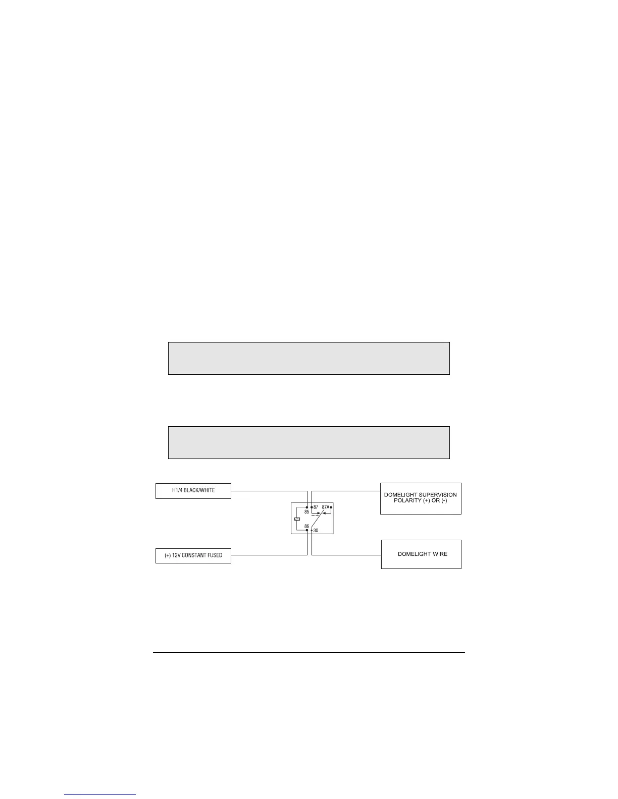
H1/4 BLACK/WHITE (-) 200 mA domelight supervision output
Connect the H1/4 wire to the optional domelight supervision relay as shown in the following diagram:
H1/5 GREEN (-) door trigger input
Most vehicles use negative door trigger circuits. Connect the green wire to a wire showing ground when
any door is opened. When connecting to newer model vehicles there is generally a need to use individ-
ual door triggers. This wire will report Zone 3.
IIMMPPOORRTTAANNTT!!
This output is only intended to drive a relay. It cannot be connected directly
to the domelight circuit, as the output cannot support the current draw of one or more bulbs.
IIMMPPOORRTTAANNTT!!
Never use this wire to drive anything but a relay or a low-current input! This
transistorized output can only supply 200 mA, and connecting directly to a solenoid, motor,
or other high-current device will cause the module to fail.
 Loading...