6
English
Operating instructions
Warning!
• Before measuring voltage, always ensure that themeter is set to thecorrect
function range and not set to current, resistance or diode test measurement.
Alwaysensure that you use thecorrect test lead socket for thetype of
measurement to bemade.
• Use extreme caution when measuring voltages over 60 V, especially when
thecircuit being measured has ahigh power output.
• Make sure that thecircuit to be measured is not “live”, i.e. conducting any current,
before connecting test leads in series with it (such as when measuring current).
• Make sure that thecircuit to be tested is not conducting any current before
performing resistance measurements or diodetests.
• Always ensure that thecorrect function and range are selected. Ifin doubt about
thecorrect range, start with thehighest and work downwards.
• Take extreme care when using themeter on aninductive component such
as atransformer, relay coils and thelike. Highvoltage may be induced at
themeasuring points if anopen circuit occurs.
• Make sure that thetest leads are in good condition with no damage to theinsulation.
• If you replace thefuse, make sure that it is thecorrect type and rating.
Voltage measurement
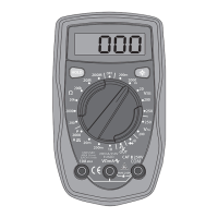
Check thebattery by rotating themultifunction selector to anew measuring function.
Thebattery symbol will appear if thebattery starts to runlow.
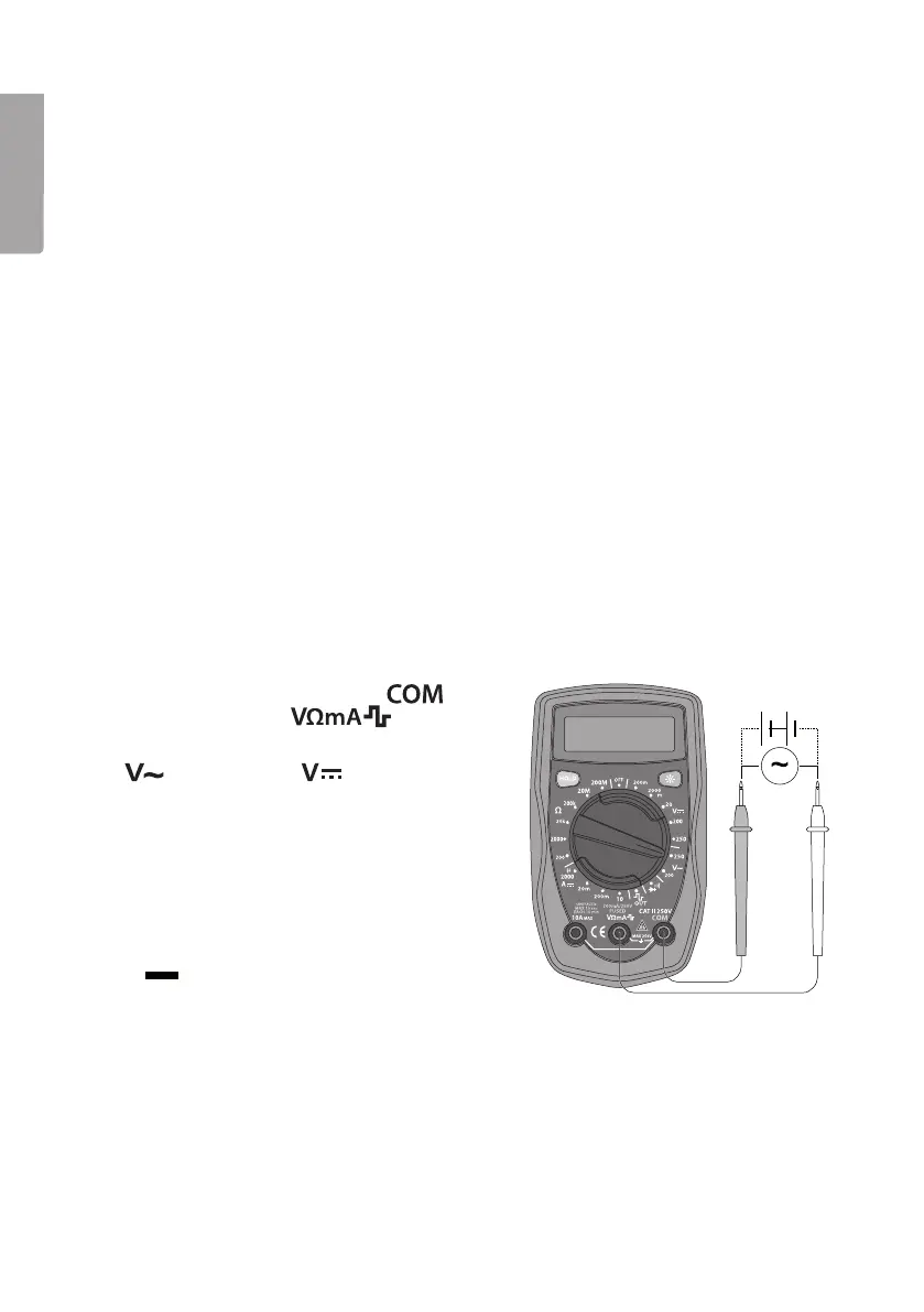
1. Connect theblack test lead to
and
thered test lead to .
2. Setthefunction selector to
(200/250 V~) or (200 mV – 250 V)
and therequired measuring range for
voltage measurement.
3. Connect thetest leads across thevoltage
source to be measured. Readthevalue.
Note: Iftheincorrect polarity is connected
when measuring DC voltages, thedisplay will
show
(minus) before thereading.
Note:
In each range, themeter has aninput impedance of 10 MΩ except themV range,
which has aninput impedance of 3000 MΩ. Thiscan cause measurement errors in
high impedance circuits. Ifthecircuit impedance is less than or equal to 10 kΩ,
theerror is negligible (0.1 % or less).