8
English
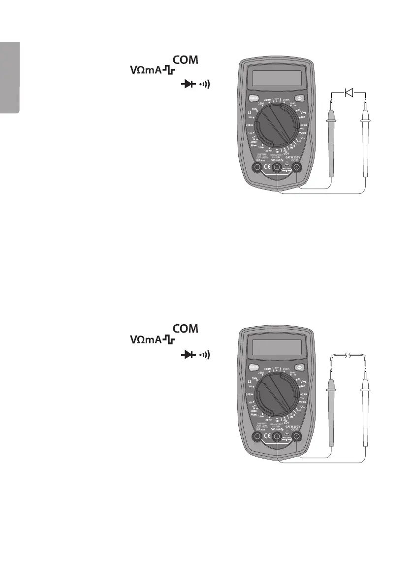
Diode testing
1. Connect theblack test lead to and
thered test lead to .
2. Setthemultifunction selector to
for measuring diode threshold value (V).
3. Connect theblack test lead to thecathode
and red test lead to theanode of thediode
to be tested. Readtheforward voltage
drop value from thedisplay. If“1” appears
on thedisplay, reverse thepolarity of
thediode.
Warning!
Make sure that thecircuit to be tested is not conducting any current before testingdiodes.
Take extreme care when using this instrument on aninductive component such as
atransformer, relay coils and thelike, and make sure they have been discharged before-
hand. Highvoltage may be induced at themeasuring points if anopen circuit occurs.
Note: Agood diode should have aforward voltage drop of from 0.5 to 0.8 V.
However,thereverse voltage drop reading can vary considerably depending on
theresistance to other paths of conductance between thetips of thetestleads.
Continuity measurement
1. Connect theblack test lead to and
thered test lead to
.
2. Setthemultifunction selector to
.
3. Connect theends of thetest leads to
theends of thecables to be tested.
- No break in thecable: Thebuzzer
sounds continuously if theresistance is
<10Ω.
- Break in thecable: Thebuzzer does not
sound if theresistance is >70Ω.
Warning!
Make sure that thecircuit to be tested is not
conducting any current before testing for
continuity.