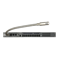
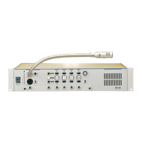
ICS-2003 INTERCOM STATION
2-11
CONFIGURATION
Assign each station’s name and other parameters by using the Eclipse
Configuration System Program (see Eclipse Configuration System Manual for
more information). Also refer to the Operation chapter for details regarding the
configuration options available from the ICS-2003’s menus.
ACCESSORY PANELS
The following sections describes how to install the following optional, accessory
key panels:
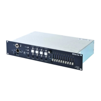
• The XPL-12 Display Expansion Panel adds 10 talk/listen selectors to a station.
• The XPL-22 Display Expansion Panel adds 20 talk/listen selectors to a station.
The installation procedure is identical for these two panels.
XPL TYPE EXPANSION PANELS
The XPL series provides selectors labeled with electronic displays that are
automatically updated whenever changes are made.
Only one rack unit (1RU) of a standard Electronics Industry Association
equipment rack is required for each expansion panel. The panels’ compact size
makes them ideal for use in TV control rooms, edit suites, mobile OB vans, and
any other location where many talk/listen keys are necessary but space it at a
premium.
Model XPL-12 provides 10 additional selectors with displays and model XPL-22
provides 20 additional selectors with displays. Each station can accept a
maximum of 60 additional selectors.
MOUNTING
All accessory panels are mounted in a standard 19-inch wide (48.3 cm) standard
Electronics Industry Association rack, requiring one unit of rack space each.
Leave at least 2 in. (51 mm) of clearance behind the rear of the chassis to allow
for cable connectors.
POWER
Each XPL panel is powered by an external AC transformer (included). Confirm
that the transformer is correct for the line voltage being used. To connect the AC
power transformer to an XPL panel, route the transformer’s secondary lead to the
“AC Power Input” connector on the back of the panel. This is a 2.1 mm coax
connector. When routing the lead, use the lead stress relief on the back of the
panel. The panel can be powered by any 12- to 16-V RMS AC source rated for
750 mA.