CFV Startup Guide
4 Part No. 750-288
1.2 Gas Piping
A manually operated shut-off valve and pressure regulator are provided
as standard on the Model CFV boiler. It is recommended to install an
approved gas filter or strainer in the gas supply line to the boiler. Please
inquire with the local gas supply company.
The boiler shall be installed such that the gas ignition system
components are protected from water (dripping, spraying, etc.) during
appliance operation and service.
If building supply gas pressure is greater than 1 psig (27.8” WC), an
upstream regulator with overpressure protection and proper gas venting
will be required and must be piped to a safe point of discharge.
All gas piping and components to the boiler gas train connection must
comply with NFPA 54, local codes, and utility requirements as a
minimum. Only gas approved fittings, valves, or pipe should be used.
Standard industry practice for gas piping is normally Schedule 40
black iron pipe and fittings.
See Table 1 for CFV gas pressure requirements.
1.3 Flue Gas Connection
The flue gases from the ClearFire boiler are removed via a gas-tight, temperature and corrosion resistant flue
gas pipeline. Only flue gas systems approved and tested by the relevant region or province are to be connected
to the ClearFire boiler. Refer to flue piping manufacturer for proper installation and sealing instructions.
See also Chapter 3 in the CFV Operation and Maintenance manual.
Boiler room ambient conditions
Relative humidity
< 85% non-condensing
Ambient temperature range 0
o
C to 50
o
C / 32
o
F to 122
o
F
Storage temperature range -20
o
C to 60
o
C / -4
o
F to 140
o
F
Combustion air temperature 0
o
C to 50
o
C / 32
o
F to 122
o
F
Specifications
Input power 115 VAC single phase 60Hz
Recommended operating steam
pressure
75-135 psig
Gas pressure requirements See Table 1
Table 1 CFV gas pressure requirements
Boiler HP Minimum pressure required
at gas train connection
Max. pressure
9.5 7.2" w.c.
28” w.c.
10 7.2" w.c.
15 7.3" w.c.
20 7.5" w.c.
25 7.7" w.c.
30 8.5" w.c.
40 11.0" w.c.
50 10.0" w.c.
60 10.0" w.c.
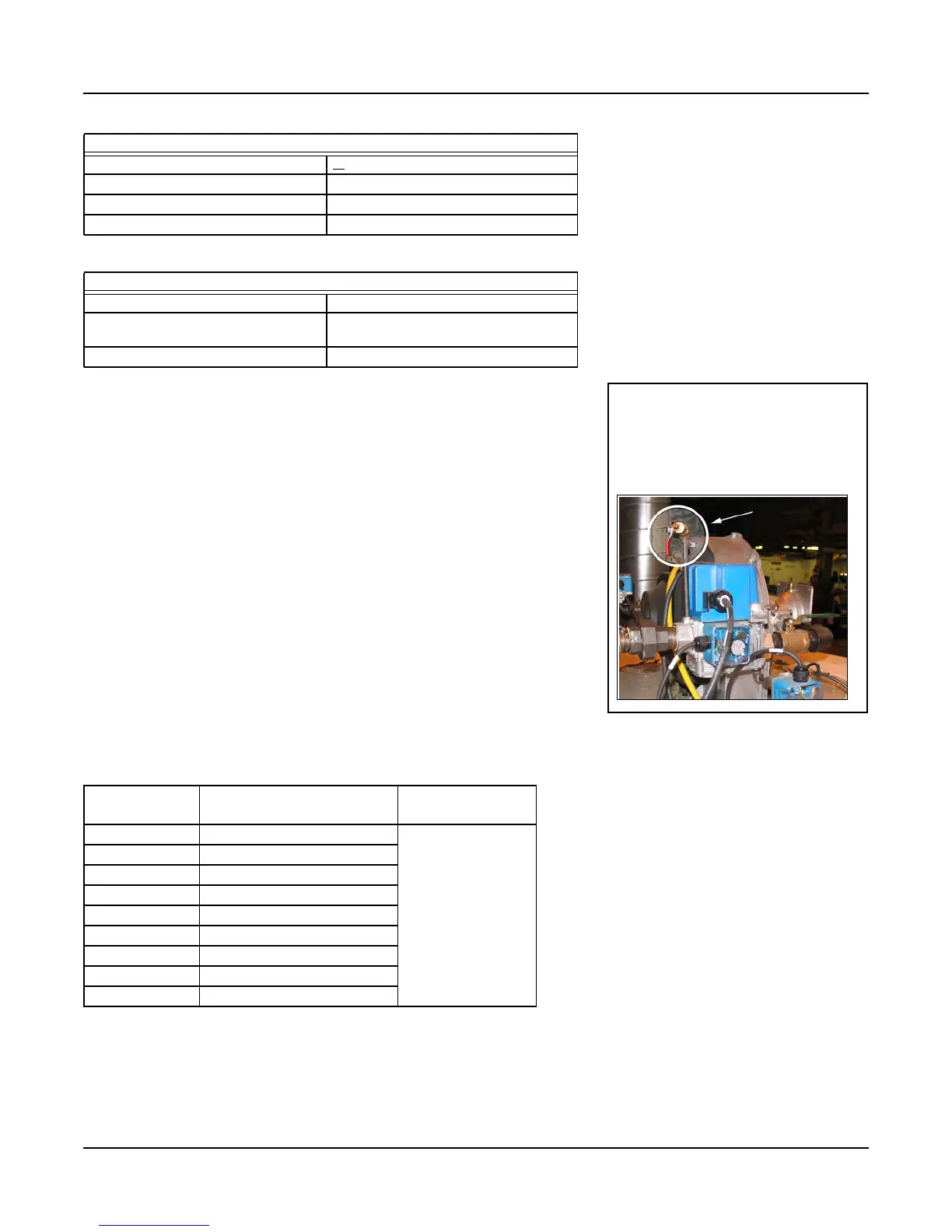
Note: To measure supply pressure
at the CFV gas valve, use the
test port on the valve inlet
flange (see below). Do not
use the leak test cocks to
measure gas pressure.