Section 2 — Installation
Part No. 750-263 2-7
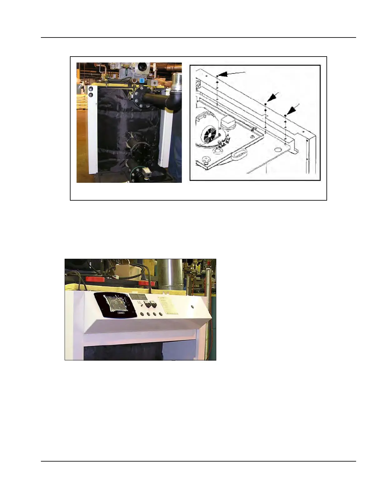
18.Remove control panel from box. Uncoil sensor wires and route wires out
of left-hand side of panel.
19.Mount control panel on front of boiler (Figure 2-11). Make sure to route
sensor wires in wiring channel on left-hand side of the boiler (see also
Figure 2-41).
20.Connect control wiring (Figure 2-12):
• Connect flame rod cable (A) to stand alone electrode on right
(includes burner ground connection).
• Connect ignition cables (B) to dual igniter electrode.
• Connect remaining connectors per connection diagram (see
Figure 2-41).
Figure 2-10
Figure 2-11