Chapter 2 Profire V Burner
2-44 750-177
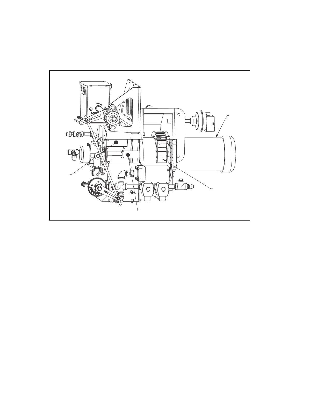
AIR HANDLING SYSTEM
A balanced blower wheel requires minimal maintenance. Check
for dirt buildup and clean the blades as
required. Inspect the impeller hub and blades for cracks. Replace if any are noticed. Make sure the air inlet
cone fits inside the impeller.
BLOWER
MOTOR
IMPELLER
WHEEL
FLEXIBLE
COUPLING
ACCESS
COVER
656-10212-000
Figure 2-28: Air Handling System
IMPELLER AND INLET CONE
Proper clearance between the impeller and the inlet housing set at 3/8” nominal. Adjust the
inlet cone so itis
centered in the inlet of the impeller and tighten the bolts. There should be no contact between the inlet cone
and the impeller. Inserting a bar through the impeller blade and using it as a lever will only damage the blade.
FIRING HEAD INSPECTION
Open side access panels to view the drawer
assembly. Inspect the lead wire to the ignition electrode. It must
be firmly attached and the insulation should be clean and free of cracks. The oil nozzle should be inspected
periodically.
If fibrous material is discovered in the gas spud ports, remove the
gas spud and back flush with shop air.
Further inspection of gas piping and gasket connections must be made to isolate the contaminate source. Be
sure to orientate the gas spuds in the correct position when reassembling the gas spuds.
The drawer assembly may be removed for
inspection and/or service. For drawer assembly drawings, refer to
Figures 2-15 to 2-24.
1. Shut off the burner; position the switch to “Off”.
2. Shut off all electric power to the burner.
3. Disconnect the fuel lines from the drawer assembly access cover.
 Loading...


