Chapter 2 Profire V Burner
2-24 750-177
5. Re-connect the oil line and high voltage power cable to
the assembly.
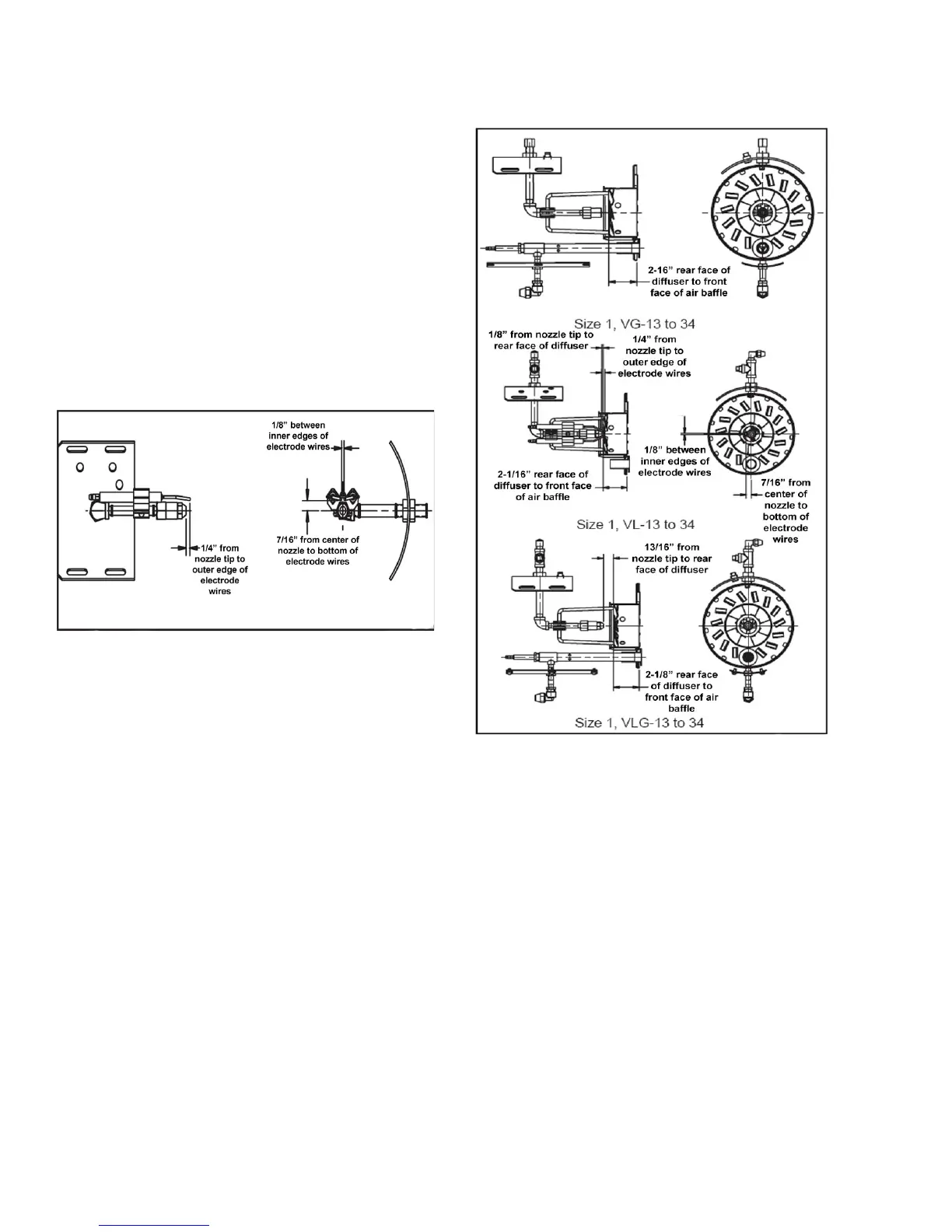
Measure the position of the diffuser to the air baffle and
compare to the following drawer assembly drawings. To
adjust:
1. Measure the distance between the leading edge of the
diffuser and the front face of the inner ring on the air
baffle assembly.
2. If adjustment is required, loosen the burner pipe locking
setscrew located on the rear cap at the top of the fan
housing, and slide the burner pipe until the correct
dimension is achieved.
3. Tighten the burner pipe locking setscrew securely.
Figure 2-18: Assembly Drawing 1
Figure 2-19: Assembly Drawing 2