Profire V Burner Chapter 2
750-177 2-5
B. Installation
DRAFT CONDITIONS
A boiler or other heating vessel fired with a V Series burner
does not depend on chimney draft for proper combustion air.
Combustion air is supplied by the burner forced draft blower
providing adequate air for any normal combustion condition.
Since draft control is essential to maximum efficiency, a draft
regulator may be required when the vessel is connected to a
tall stack or where wind conditions may cause erratic draft.
Excessive furnace draft contributes to inefficient burner
operation.
Sealed boilers may be operated under positive firebox
pressure within the capability of the burner.
COMBUSTION AIR SUPPLY
The space in which a burner operates must be supplied with
adequate fresh air for combustion and ventilation purposes.
Fresh air supply must meet or exceed all code requirements.
Consult with insurance carrier and/or local authorities for
specific regulations.
COMBUSTION CHAMBER DESIGN
The V series burners are of the forced draft flame retention
type. Refractory is required only to protect surfaces not
adequately protected by free circulating water. Four basic
objectives are:
• Provide adequate combustion space
• Avoid flame impingement
• Protect surfaces not adequately water cooled
• Seal openings
The table below shows suggested minimum combustion
chamber dimensions.
THE BOILER ROOM PRESSURE MUST BE AT
LEAST EQUAL TO THE OUTDOOR ATMOSHERIC
PRESSURE. WHERE FAN VENTILATION IS
USED, AIR MUST BE FORCED INTO THE BOILER
ROOM. NEVER EXHAUST AIR FROM THE
BOILER ROOM. ADJOINING AREAS HAVING
EXHAUST FANS MUST BE POSITIVELY ISO-
LATED FROM THE BOILER ROOM.
!
DANGER
CAUTION
!
DANGER
WARNING
S
A
G
J
C
L
C
L
C
L
MODEL A B C D E F
G
H I
J
K L M N P R S T
U
SIZE 1
32 7/8 12 3/8
4
8 1/4 3 3/4
15
9 3/4
30
9 3/4 7 3/8 12 7/8 11 1/4 6 1/2 14 3/8
13
12
5 /14 7 1/4 11 3/4
SIZE 2
37 1/3 13 5/8
4104
18 1/8
8
34 1/2 10 1/2 7 3/8
15
13 1/4 7 1/2 15 1/8 12 1/2 12 3/4 6 1/4
9
14 1/2
SIZE 3
44 3/8 16 1/8
4
11 1/2 3 3/4 17 1/2 15 3/4 41 3/4 15 1/4 7 3/8 16 3/4 15 1/4 8 3/8 17 3/8 12 1/2 14 1/8 6 1/4 10 1/4 18 5/8
SIZE 4
54 3/8 24 7/8
5
13 5/8
4
25 1/4
12
45 7/8 13 1/2 7 3/8 17 1/2 15 3/8 8 3/4 20 1/8 14 1/2
16
7 1/2 12 1/4 19 1/4
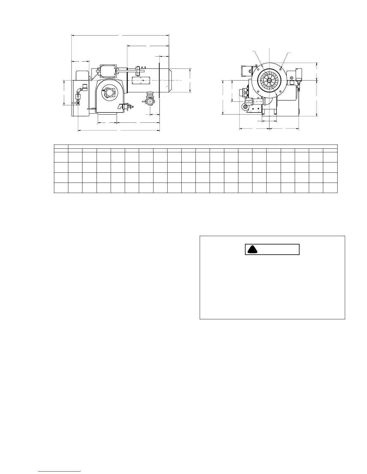
BURNER
STANDARD CONFIGURATION - REAR MOUNTED PANEL, GAS PILOT LINE PANEL MOUNTED
656-00037
C
B
H
E
F
I
D
K DIA.
M
N
PR
T
U
4X Ø3/4
L B.C.
Figure 2-3: Burner Dimensions (Inches)