Chapter 5 Adjustment Procedures
5-10 750-177
Final adjustment to fuel input must be made to produce a
minimum of smoke. A maximum smoke spot density of a No.
2 for light oil, as measured in conformance to ASTMD 2156-
63T.
Through the use of the manual flame control, slowly bring the
unit to high fire by stages while monitoring combustion for
overly rich or lean conditions. At the high fire position, the air
damper should be fully opened and the air and oil pressure
readings should be on the order of the readings given in
Chapter 5.
U. LOW OIL PRESSURE SWITCH
The L.O.P.S. prevents burner ignition, or stops its operation,
when the oil pressure is below the setpoint. Adjust the control
by turning the screw on top of control case to an indicated
pressure 10 psi below the established primary oil pressure
setting indicated on the oil supply pressure gauge. The switch
will remain in a closed position as long as the oil pressure
exceeds this setting. The control normally used automatically
resets when pressure is restored after a drop.
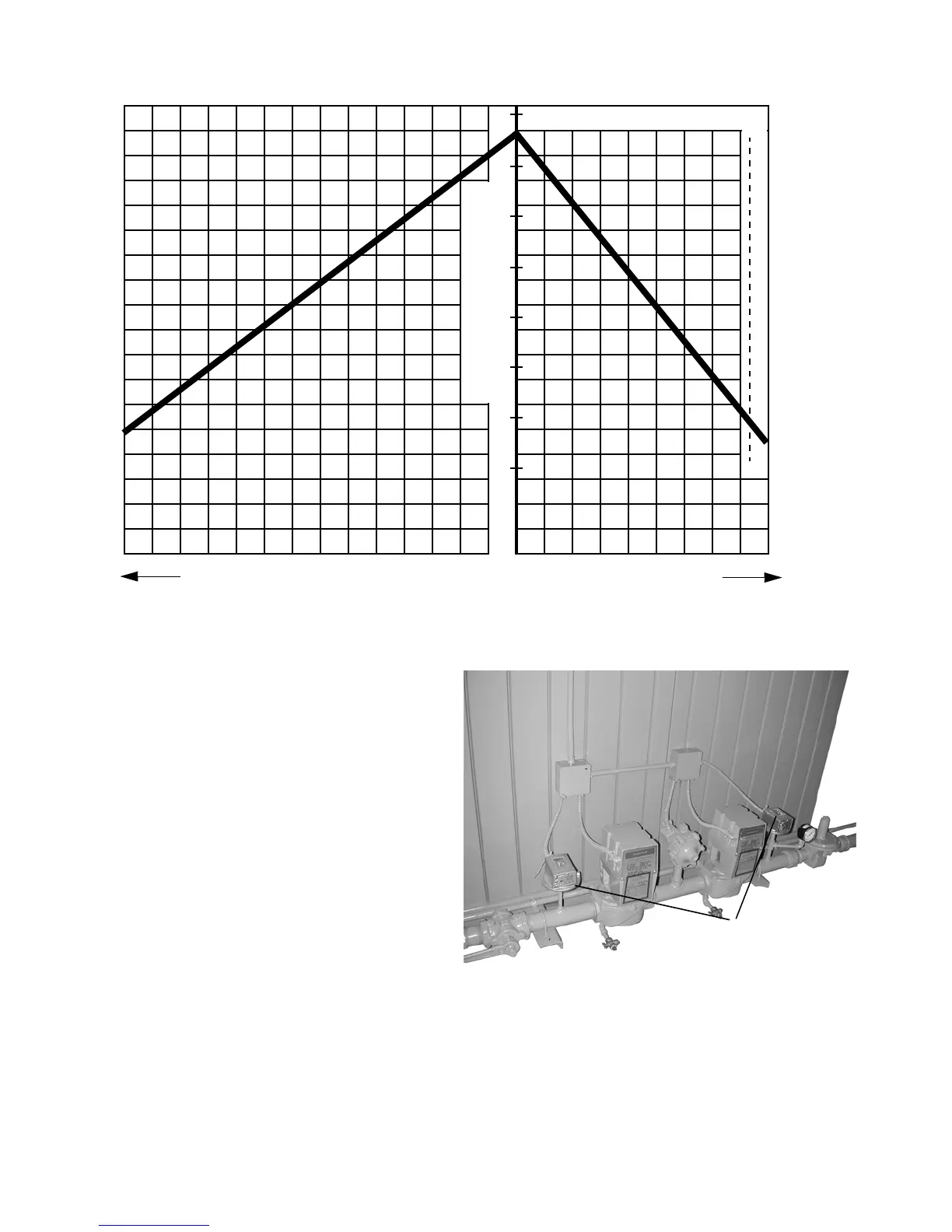
PER CENT O
2
IN FLUE GAS PER CENT CO
PER CENT EXCESS AIR
1020
3040
5060
5
6
7
8
9
10
11
12
1122334455 6
67
890
PER CENT CO
2
IN FLUE GAS
Figure 5-5: Flue Gas Analysis Chart for Natural Gas
FIRST VISIBLE TRACE OF STACK HAZE
1/10 of 1% CO = 1,000 PPM
15
Figure 5-6: Gas Train With High and Low Pressure
Switches
Pressure Switches