Chapter 5 Adjustment Procedures
5-6 750-177
L. LOW WATER CUTOFF DEVICES
(Steam and Hot Water)
No adjustment is required since LWCO controls are preset by
the original manufacturer. However, if the water level is not
maintained, inspect the devices immediately and replace as
required.
M. COMBUSTION AIR PROVING
SWITCH
Air pressure against the diaphragm actuates the switch which,
when made, completes a circuit to prove the presence of
combustion air. Since the pressure of the combustion air is at
its minimum value when the damper is full closed, the switch
should be adjusted under that situation. It should be set
slightly below the minimum pressure, but not too close to that
point to cause nuisance shutdowns.
The run/test switch on the program relay should be set to
TEST. Turn the burner switch on. The blower will start
(provided that all limit circuits are completed) and the
programmer will remain in the low-fire (damper closed)
portion of the prepurge.
Slowly turn down the air switch adjusting screw until it
breaks the circuit. Here the programmer will lock out and
must be manually reset before it can be restarted. Add a half
turn or so to the adjusting screw to remake its circuit.
Recycle the program relay to be sure that normal operation is
obtained. Return the test switch to the RUN position.
N. GAS PILOT FLAME ADJUSTMENT
The size of the gas pilot flame is regulated by adjusting the
gas flow through the pilot gas regulator. The flame must be
sufficient to ignite the main flame and to be seen by the flame
detector. But an extremely large flame is not required. An
overly rich flame can cause sooting or carbon buildup on the
igniting electrode. Too small a flame can cause ignition
problems.
Although it is possible to visibly adjust the size of the pilot
flame, it is preferable to obtain a microamp or voltage reading
of the flame signal.
The correct voltage or microamp readings can be found in the
information supplied with the flame safeguard system.
The program relay used may be of the type that provides
message information that includes a constant flame signal of
dc voltage. In this case a separate dc voltmeter is not required.
O. GAS PRESSURE AND FLOW
INFORMATION
Because of variables in both the properties of gas and the
supply system, it will be necessary to regulate the pressure of
the gas to a level that produces a steady, dependable flame
that yields highest combustion efficiency at rated
performance yet prevents overfiring. Once the optimum
pressure has been established, it should be recorded and
periodic checks made to verify that the regulator is holding
the pressure at this level. Occasional modification in fuel
composition or pressure by the supplier may, at times, require
readjustment to return the burner to peak efficiency.
Pressure
The gas supplied must provide not only the quantity of gas
demanded by the unit, but must also be at a pressure high
enough to overcome the pressure-loss due to the frictional
resistance imposed by the burner system and the control
valves.
The pressure required at the entrance to the burner gas train
for rated boiler output is termed “inlet pressure.” The gas
pressure regulator must be adjusted to achieve the pressure to
assure full input.
The inlet pressure requirement varies with boiler size, and
types of gas train. Refer to Table 6-3 for pressure require-
ments.
The pressures listed are based on 1000 Btu/cu-ft natural gas
at elevations up to 700 feet above sea level.
The volume of gas flow is measured in terms of cubic feet and
is determined by a meter reading. The gas flow rate required
for maximum boiler output depends on the heating value
(Btu/cu-ft) of the gas supplied (Table 6-1).
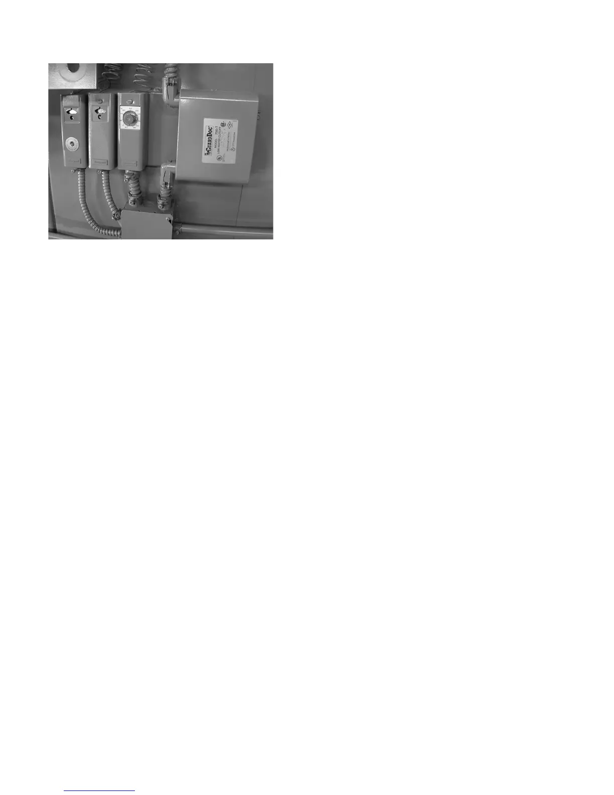
1. HIGH LIMIT TEMPERATURE CONTROL
2.
OPERATING LIMIT TEMPERATURE CONTROL
3. MODULATING TEMPERATURE CONTROL
123
Figure 5-4: Steam Operating Controls