Chapter 1 GENERAL DESCRIPTION
1-2 750-177
B. The Boiler
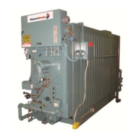
The Cleaver-Brooks Model FLX is a five-pass steel boiler
with flexible watertubes formed and arranged so as to direct
the flow of combustion gases through the boiler. The pressure
vessel conforms to Section I or IV of the ASME code. The
pressure vessel consists of the formed tubes, the external
downcomer, and the top and bottom drums to which they
connect. The heated area of the pressure vessel is contained
within a gas tight insulated casing that is composed of
removable formed steel panels.
Always order genuine Cleaver-Brooks parts from your
local Cleaver-Brooks authorized representative.
The boiler and related equipment installation are to be in
compliance with the standards of the National Board of Fire
Underwriters. Installation should also conform to state and
local codes governing such equipment. Prior to installation,
the proper authorities having jurisdiction are to be consulted,
permits obtained, etc. All boilers in the above series comply,
when equipped with optional equipment, to Industrial Risk
Insurers (IRI), Factory Mutual (FM), or other insuring
underwriters requirements.
The Model FLX boiler is a packaged watertube boiler of
welded steel construction and consists of a pressure vessel,
burner, burner controls, forced draft fan, damper, refractory,
and appropriate boiler trim.
Hot water is commonly used in heating applications with the
boiler supplying water to the system at 180 °F to 220 °F. The
operating pressure for hot water heating systems usually is
30 psig to 125 psig.
Steam boilers are designed for low and high pressure appli-
cations. Low pressure boilers are limited to 15 psig design
pressure, and are typically used for heating applications.
High pressure boilers are limited to 150 psig design pressure,
and are typically used for process steam applications.
Steam and hot water boilers are defined according to design
pressure and operating pressure. Design pressure is the max-
imum pressure used in the design of the boiler for the pur-
pose of calculating the minimum permissible thickness or
physical characteristics of the pressure vessel parts of the
boiler. Typically, the safety valves are set at or below design
pressure. Operating pressure is the pressure of the boiler at
which it normally operates. The operating pressure usually is
maintained at a suitable level below the setting of the pres-
sure relieving valve(s) to prevent their frequent opening dur-
ing normal operation.
The type of service that your boiler is required to provide has
an important bearing on the amount of waterside care it will
require.
!
DANGER
CAUTION
Waterside care is of prime importance. For
specific information or assistance with your
water treatment requirements, contact your
Cleaver-Brooks service and parts represen-
tative. Failure to follow these instructions
could result in equipment damage.
Feedwater equipment should be checked and ready for use.
Be sure that all valves, piping, boiler feed pumps, and
receivers are installed in accordance with prevailing codes
and practices.
Water requirements for both steam and hot water boilers are
essential to boiler life and length of service. Constant
attention to water requirements will pay dividends in the form
of longer life, less down-time, and prevention of costly
repairs. Care taken in placing the pressure vessel into initial
service is vital. The waterside of new boilers and new or
remodeled steam or hot water systems may contain oil, grease
or other foreign matter. A method of boiling out the vessel to
remove accumulations is described in Chapter 3.
The operator should be familiar with Chapter 3 before
attempting to place the unit into operation.
C. Construction
Steam boilers designed for 15 psig and hot water boilers
designed for 250°F at 160 psi or less are constructed in
accordance with Section IV, Heating Boilers, of ASME Code.
Steam boilers designed for 150 psig are constructed in
accordance with Section I, Power Boilers, of the ASME
Code.
D. Steam Controls (All Fuels)
1. Operating Limit Pressure Control (Figures 1-2 and 1-3):
Breaks a circuit to stop burner operation on a rise of
boiler pressure at a selected setting. It is adjusted to stop
or start the burner at a preselected pressure setting.
2. High Limit Pressure Control (Figure 1-2 and 1-3):
Breaks a circuit to stop burner operation on a rise of
pressure above a selected setting. It is adjusted to stop the
burner at a preselected pressure above the operating limit
control setting. The high limit pressure control is
equipped with a manual reset.
 Loading...


